Under the term Feature Extraction we include several techniques aiming to detect or extract information of
low level of abstraction from images. These features can be objects : points, lines, etc. They can also be
measures : moments, textures, etc.
This example illustrates the use of the otb::ScalarImageToTexturesFilter , which compute the
standard Haralick’s textural features [56] presented in table 14.1.1, where μt and σt are the mean and
standard deviation of the row (or column, due to symmetry) sums, μ = (weighted pixel average)
= ∑i,ji⋅g(i,j) = ∑i,jj⋅g(i,j) due to matrix summetry, and σ = (weighted pixel variance)
= ∑i,j(i-μ)2 ⋅g(i,j) = ∑i,j(j-μ)2 ⋅g(i,j) due to matrix symmetry.
|
|
| | |
| Energy | f1 = ∑i,jg(i,j)2 |
| | |
|
|
| | |
| Entropy | f2 = -∑i,jg(i,j)log2g(i,j), or 0 if g(i,j) = 0 |
| | |
|
|
| | |
| Correlation | f3 = ∑i,j |
| | |
|
|
| | |
| Difference Moment | f4 = ∑i,j g(i,j) g(i,j) |
| | |
|
|
| | |
| Inertia (a.k.a. Contrast) | f5 = ∑i,j(i-j)2g(i,j) |
| | |
|
|
| | |
| Cluster Shade | f6 = ∑i,j((i-μ)+(j-μ))3g(i,j) |
| | |
|
|
| Cluster Prominence | f7 = ∑i,j((i-μ)+(j-μ))4g(i,j) |
| | |
|
|
| | |
| Haralick’s Correlation | f8 =  |
| | |
|
|
| |
More features are available in otb::ScalarImageToAdvancedTexturesFilter . The following classes
provide similar functionality:
The source code for this example can be found in the file
Examples/FeatureExtraction/TextureExample.cxx.
The first step required to use the filter is to include the header file.
#include "otbScalarImageToTexturesFilter.h"
After defining the types for the pixels and the images used in the example, we define the types for the
textures filter. It is templated by the input and output image types.
typedef otb::ScalarImageToTexturesFilter <ImageType, ImageType> TexturesFilterType;
We can now instantiate the filters.
TexturesFilterType::Pointer texturesFilter = TexturesFilterType::New();
The texture filters takes at least 2 parameters: the radius of the neighborhood on which the texture
will be computed and the offset used. Texture features are bivariate statistics, that is, they are
computed using pair of pixels. Each texture feature is defined for an offset defining the pixel
pair.
The radius parameter can be passed to the filter as a scalar parameter if the neighborhood is square, or as
SizeType in any case.
The offset is always an array of N values, where N is the number of dimensions of the image.
typedef ImageType::SizeType SizeType; SizeType sradius; sradius.Fill(radius);
texturesFilter->SetRadius(sradius); typedef ImageType::OffsetType OffsetType; OffsetType offset;
offset[0] = xOffset; offset[1] = yOffset; texturesFilter->SetOffset(offset);
The textures filter will automatically derive the optimal bin size for co-occurences histogram, but
they need to know the input image minimum and maximum. These values can be set like this :
texturesFilter->SetInputImageMinimum(0); texturesFilter->SetInputImageMaximum(255);
To tune co-occurence histogram resolution, you can use the SetNumberOfBinsPerAxis() method.
We can now plug the pipeline.
texturesFilter->SetInput(reader->GetOutput()); writer->SetInput(texturesFilter->GetInertiaOutput());
writer->Update();
Figure 14.1 shows the result of applying the contrast texture computation.
The source code for this example can be found in the file
Examples/FeatureExtraction/PanTexExample.cxx.
This example illustrates the use of the otb::ScalarImageToPanTexTextureFilter . This texture
parameter was first introduced in [107] and is very useful for urban area detection. The following classes
provide similar functionality:
The first step required to use this filter is to include its header file.
#include "otbScalarImageToPanTexTextureFilter.h"
After defining the types for the pixels and the images used in the example, we define the type for the PanTex
filter. It is templated by the input and output image types.
typedef otb::ScalarImageToPanTexTextureFilter <ImageType, ImageType> PanTexTextureFilterType;
We can now instatiate the filter.
PanTexTextureFilterType::Pointer textureFilter = PanTexTextureFilterType::New();
Then, we set the parameters of the filter.The radius of the neighborhood to compute the texture. The number
of bins per axis for histogram generation (it is the size of the co-occurrence matrix). Moreover, we have to
specify the Min/Max in the input image. In the example, image Min/Max is set by the user to 0 and 255.
Alternatively you can use the class itk::MinimumMaximumImageCalculator to calculate these
values.
PanTexTextureFilterType::SizeType sradius; sradius.Fill(4);
textureFilter->SetNumberOfBinsPerAxis(8); textureFilter->SetRadius(sradius);
textureFilter->SetInputImageMinimum(0); textureFilter->SetInputImageMaximum(255);
We can now plug the pipeline and trigger the execution by calling the Update method of the
writer.
textureFilter->SetInput(reader->GetOutput()); writer->SetInput(textureFilter->GetOutput()); writer->Update();
Figure 14.2 shows the result of applying the PanTex computation.
The source code for this example can be found in the file
Examples/FeatureExtraction/SFSExample.cxx.
This example illustrates the use of the otb::SFSTexturesImageFilter . This filter computes the
Structural Feature Set as described in [61]. These features are textural parameters which give information
about the structure of lines passing through each pixel of the image.
The first step required to use this filter is to include its header file.
#include "otbSFSTexturesImageFilter.h"
As with every OTB program, we start by defining the types for the images, the readers and the
writers.
typedef otb::Image<PixelType, Dimension> ImageType; typedef otb::ImageFileReader<ImageType> ReaderType;
typedef otb::ImageFileWriter<ImageType> WriterType;
The we can instantiate the type for the SFS filter, which is templated over the input and output pixel
types.
typedef otb::SFSTexturesImageFilter<ImageType, ImageType> SFSFilterType;
After that, we can instantiate the filter. We will also instantiate the reader and one writer for each output
image, since the SFS filter generates 6 different features.
SFSFilterType::Pointer filter = SFSFilterType::New(); ReaderType::Pointer reader = ReaderType::New();
WriterType::Pointer writerLength = WriterType::New(); WriterType::Pointer writerWidth = WriterType::New();
WriterType::Pointer writerWMean = WriterType::New(); WriterType::Pointer writerRatio = WriterType::New();
WriterType::Pointer writerSD = WriterType::New(); WriterType::Pointer writerPsi = WriterType::New();
The SFS filter has several parameters which have to be selected. They are:
- a spectral threshold to decide if 2 neighboring pixels are connected;
- a spatial threshold defining the maximum length for an extracted line;
- the number of directions which will be analyzed (the first one is to the right and they are
equally distributed between 0 and 2π);
- the α parameter fort the ω-mean feature;
- the RatioMax parameter fort the ω-mean feature.
filter->SetSpectralThreshold(spectThresh); filter->SetSpatialThreshold(spatialThresh);
filter->SetNumberOfDirections(dirNb); filter->SetRatioMaxConsiderationNumber(maxConsideration);
filter->SetAlpha(alpha);
In order to disable the computation of a feature, the SetFeatureStatus parameter can be used. The true
value enables the feature (default behavior) and the false value disables the computation. Therefore, the
following line is useless, but is given here as an example.
filter->SetFeatureStatus(SFSFilterType::PSI, true);
Now, we plug the pipeline using all the writers.
filter->SetInput(reader->GetOutput()); writerLength->SetFileName(outNameLength);
writerLength->SetInput(filter->GetLengthOutput()); writerLength->Update();
writerWidth->SetFileName(outNameWidth); writerWidth->SetInput(filter->GetWidthOutput());
writerWidth->Update(); writerWMean->SetFileName(outNameWMean);
writerWMean->SetInput(filter->GetWMeanOutput()); writerWMean->Update();
writerRatio->SetFileName(outNameRatio); writerRatio->SetInput(filter->GetRatioOutput());
writerRatio->Update(); writerSD->SetFileName(outNameSD);
writerSD->SetInput(filter->GetSDOutput()); writerSD->Update(); writerPsi->SetFileName(outNamePsi);
writerPsi->SetInput(filter->GetPSIOutput()); writerPsi->Update();
Figure 14.3 shows the result of applying the SFS computation to an image
The source code for this example can be found in the file
Examples/FeatureExtraction/HarrisExample.cxx.
This example illustrates the use of the otb::HarrisImageFilter .
The first step required to use this filter is to include its header file.
The otb::HarrisImageFilter is templated over the input and output image types, so we start by
defining:
typedef otb::HarrisImageFilter<InputImageType, InputImageType> HarrisFilterType;
The otb::HarrisImageFilter needs some parameters to operate. The derivative computation is
performed by a convolution with the derivative of a Gaussian kernel of variance σD (derivation scale) and
the smoothing of the image is performed by convolving with a Gaussian kernel of variance σI (integration
scale). This allows the computation of the following matrix:
![2 [ L2x(x,σD ) LxLy(x,σD) ]
μ(x,σI,σD)= σDg(σI)⋆ LxLy(x,σD) L2y(x,σD)](SoftwareGuide222x.png) | (14.1) |
The output of the detector is
harris->SetSigmaD(SigmaD); harris->SetSigmaI(SigmaI); harris->SetAlpha(Alpha);
Figure 14.4 shows the result of applying the interest point detector to a small patch extracted from
a Spot 5 image.
The output of the otb::HarrisImageFilter is an image where, for each pixel, we obtain the
intensity of the detection. Often, the user may want to get access to the set of points for which
the output of the detector is higher than a given threshold. This can be obtained by using the
otb::HarrisImageToPointSetFilter . This filter is only templated over the input image type, the output
being a itk::PointSet with pixel type equal to the image pixel type.
typedef otb::HarrisImageToPointSetFilter<InputImageType> FunctionType;
We declare now the filter and a pointer to the output point set.
typedef FunctionType::OutputPointSetType OutputPointSetType;
FunctionType::Pointer harrisPoints = FunctionType::New();
OutputPointSetType::Pointer pointSet = OutputPointSetType::New();
The otb::HarrisImageToPointSetFilter takes the same parameters as the otb::HarrisImageFilter
and an additional parameter : the threshold for the point selection.
harrisPoints->SetInput(0, reader->GetOutput()); harrisPoints->SetSigmaD(SigmaD);
harrisPoints->SetSigmaI(SigmaI); harrisPoints->SetAlpha(Alpha);
harrisPoints->SetLowerThreshold(10); pointSet = harrisPoints->GetOutput();
We can now iterate through the obtained pointset and access the coordinates of the points. We start by
accessing the container of the points which is encapsulated into the point set (see section 5.2 for more
information on using itk::PointSet s) and declaring an iterator to it.
typedef OutputPointSetType::PointsContainer ContainerType;
ContainerType⋆ pointsContainer = pointSet->GetPoints(); typedef ContainerType::Iterator IteratorType;
IteratorType itList = pointsContainer->Begin();
And we get the points coordinates
while (itList != pointsContainer->End()) { typedef OutputPointSetType::PointType OutputPointType;
OutputPointType pCoordinate = (itList.Value()); std::cout << pCoordinate << std::endl; ++itList; }
The source code for this example can be found in the file
Examples/FeatureExtraction/SURFExample.cxx.
This example illustrates the use of the otb::ImageToSURFKeyPointSetFilter . The Speed-Up Robust
Features (or SURF) is an algorithm in computer vision to detect and describe local features in
images. The algorithm is detailed in [10]. The applications of SURF are the same as those for
SIFT.
The first step required to use this filter is to include its header file.
#include "otbImageToSURFKeyPointSetFilter.h"
We will start by defining the required types. We will work with a scalar image of float pixels. We also define
the corresponding image reader.
typedef float RealType; typedef otb::Image<RealType, Dimension> ImageType;
typedef otb::ImageFileReader<ImageType> ReaderType;
The SURF descriptors will be stored in a point set containing the vector of features.
typedef itk::VariableLengthVector<RealType> RealVectorType;
typedef itk::PointSet<RealVectorType, Dimension> PointSetType;
The SURF filter itself is templated over the input image and the generated point set.
typedef otb::ImageToSURFKeyPointSetFilter<ImageType, PointSetType> ImageToFastSURFKeyPointSetFilterType;
We instantiate the reader.
ReaderType::Pointer reader = ReaderType::New(); reader->SetFileName(infname);
We instantiate the filter.
ImageToFastSURFKeyPointSetFilterType::Pointer filter = ImageToFastSURFKeyPointSetFilterType::New();
We plug the filter and set the number of scales for the SURF computation. We can afterwards run the
processing with the Update() method.
filter->SetInput(reader->GetOutput()); filter->SetOctavesNumber(octaves);
filter->SetScalesNumber(scales); filter->Update();
Once the SURF are computed, we may want to draw them on top of the input image. In order to do this, we
will create the following RGB image and the corresponding writer:
typedef unsigned char PixelType;
typedef itk::RGBPixel<PixelType> RGBPixelType;
typedef otb::Image<RGBPixelType, 2> OutputImageType;
typedef otb::ImageFileWriter<OutputImageType> WriterType;
OutputImageType::Pointer outputImage = OutputImageType::New();
We set the regions of the image by copying the information from the input image and we allocate the
memory for the output image.
outputImage->SetRegions(reader->GetOutput()->GetLargestPossibleRegion()); outputImage->Allocate();
We can now proceed to copy the input image into the output one using region iterators. The input image is a
grey level one. The output image will be made of color crosses for each SURF on top of the grey level
input image. So we start by copying the grey level values on each of the 3 channels of the color
image.
itk::ImageRegionIterator<OutputImageType> iterOutput( outputImage, outputImage->
GetLargestPossibleRegion()); itk::ImageRegionIterator<ImageType> iterInput(reader->GetOutput(),
reader->GetOutput()->
GetLargestPossibleRegion());
for (iterOutput.GoToBegin(), iterInput.GoToBegin(); !iterOutput.IsAtEnd();
++iterOutput, ++iterInput) { OutputImageType::PixelType rgbPixel;
rgbPixel.SetRed(static_cast<PixelType>(iterInput.Get()));
rgbPixel.SetGreen(static_cast<PixelType>(iterInput.Get()));
rgbPixel.SetBlue(static_cast<PixelType>(iterInput.Get())); iterOutput.Set(rgbPixel); }
We are now going to plot color crosses on the output image. We will need to define offsets (top, bottom, left
and right) with respect to the SURF position in order to draw the cross segments.
ImageType::OffsetType t = {{ 0, 1}}; ImageType::OffsetType b = {{ 0, -1}};
ImageType::OffsetType l = {{ 1, 0}}; ImageType::OffsetType r = {{-1, 0}};
Now, we are going to access the point set generated by the SURF filter. The points are stored into a points
container that we are going to walk through using an iterator. These are the types needed for this
task:
typedef PointSetType::PointsContainer PointsContainerType;
typedef PointsContainerType::Iterator PointsIteratorType;
We set the iterator to the beginning of the point set.
PointsIteratorType pIt = filter->GetOutput()->GetPoints()->Begin();
We get the information about image size and spacing before drawing the crosses.
ImageType::SpacingType spacing = reader->GetOutput()->GetSignedSpacing();
ImageType::PointType origin = reader->GetOutput()->GetOrigin();
//OutputImageType::SizeType size = outputImage->GetLargestPossibleRegion().GetSize();
And we iterate through the SURF set:
while (pIt != filter->GetOutput()->GetPoints()->End()) {
We get the pixel coordinates for each SURF by using the Value() method on the point set iterator. We use
the information about size and spacing in order to convert the physical coordinates of the point into pixel
coordinates.
ImageType::IndexType index; index[0] = static_cast<unsigned int>(vcl_floor(
static_cast<double>(
(pIt.Value()[0] -
origin[0]) / spacing[0] + 0.5
))); index[1] = static_cast<unsigned int>(vcl_floor(
static_cast<double>(
(pIt.Value()[1] -
origin[1]) / spacing[1] + 0.5
)));
We create a green pixel.
OutputImageType::PixelType keyPixel; keyPixel.SetRed(0); keyPixel.SetGreen(255);
keyPixel.SetBlue(0);
We draw the crosses using the offsets and checking that we are inside the image, since SURFs on the image
borders would cause an out of bounds pixel access.
if (outputImage->GetLargestPossibleRegion().IsInside(index)) {
outputImage->SetPixel(index, keyPixel); if (outputImage->GetLargestPossibleRegion().IsInside(index +
t)) outputImage->
SetPixel(index + t, keyPixel); if (outputImage->GetLargestPossibleRegion().IsInside(index +
b)) outputImage->
SetPixel(index + b, keyPixel); if (outputImage->GetLargestPossibleRegion().IsInside(index +
l)) outputImage->
SetPixel(index + l, keyPixel); if (outputImage->GetLargestPossibleRegion().IsInside(index +
r)) outputImage->
SetPixel(index + r, keyPixel); } ++pIt; }
Finally, we write the image.
WriterType::Pointer writer = WriterType::New(); writer->SetFileName(outputImageFilename);
writer->SetInput(outputImage); writer->Update();
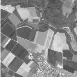
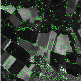
Figure 14.5 shows the result of applying the SURF point detector to a small patch extracted from a
Spot 5 image.
The source code for this example can be found in the file
Examples/FeatureExtraction/AlignmentsExample.cxx.
This example illustrates the use of the otb::ImageToPathListAlignFilter . This filter allows
extracting meaningful alignments. Alignments (that is edges and lines) are detected using the Gestalt
approach proposed by Desolneux et al. [39]. In this context, an event is considered meaningful if the
expectation of its occurrence would be very small in a random image. One can thus consider that in a
random image the direction of the gradient of a given point is uniformly distributed, and that neighbouring
pixels have a very low probability of having the same gradient direction. This algorithm gives a set of
straight line segments defined by the two extremity coordinates under the form of a std::list of
itk::PolyLineParametricPath.
The first step required to use this filter is to include its header.
#include "otbImageToPathListAlignFilter.h"
In order to visualize the detected alignments, we will use the facility class otb::DrawPathFilter which
draws a itk::PolyLineParametricPath on top of a given image.
#include "itkPolyLineParametricPath.h" #include "otbDrawPathFilter.h"
The otb::ImageToPathListAlignFilter is templated over the input image type and the output path
type, so we start by defining:
typedef itk::PolyLineParametricPath<Dimension> PathType;
typedef otb::ImageToPathListAlignFilter<InputImageType, PathType> ListAlignFilterType;
Next, we build the pipeline.
ListAlignFilterType::Pointer alignFilter = ListAlignFilterType::New();
alignFilter->SetInput(reader->GetOutput());
We can choose the number of accepted false alarms in the detection with the method SetEps() for which
the parameter is of the form -log10(max. number of false alarms).
alignFilter->SetEps(atoi(argv[3]));
As stated, above, the otb::DrawPathFilter , is useful for drawint the detected alignments. This class is
templated over the input image and path types and also on the output image type.
typedef otb::DrawPathFilter<InputImageType, PathType, OutputImageType> DrawPathFilterType;
We will now go through the list of detected paths and feed them to the otb::DrawPathFilter inside a
loop. We will use a list iterator inside a while statement.
typedef ListAlignFilterType::OutputPathListType ListType;
ListType⋆ pathList = alignFilter->GetOutput(); ListType::Iterator listIt = pathList->Begin();
We define a dummy image will be iteratively fed to the otb::DrawPathFilter after the drawing of each
alignment.
InputImageType::Pointer backgroundImage = reader->GetOutput();
We iterate through the list and write the result to a file.
while (listIt != pathList->End()) { DrawPathFilterType::Pointer drawPathFilter = DrawPathFilterType::New();
drawPathFilter->SetImageInput(backgroundImage); drawPathFilter->SetInputPath(listIt.Get());
drawPathFilter->SetValue(itk::NumericTraits<OutputPixelType>::max()); drawPathFilter->Update();
backgroundImage = drawPathFilter->GetOutput(); ++listIt; } writer->SetInput(backgroundImage);
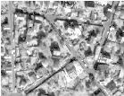
Figure 14.6 shows the result of applying the alignment detection to a small patch extracted from a
VHR image.
The source code for this example can be found in the file
Examples/FeatureExtraction/RatioLineDetectorExample.cxx.
This example illustrates the use of the otb::RatioLineDetectorImageFilter . This filter is
used for line detection in SAR images. Its principle is described in [131]: a line is detected if
two parallel edges are present in the images. These edges are detected with the ratio of means
detector.
The first step required to use this filter is to include its header file.
#include "otbLineRatioDetectorImageFilter.h"
Then we must decide what pixel type to use for the image. We choose to make all computations
with floating point precision and rescale the results between 0 and 255 in order to export PNG
images.
typedef float InternalPixelType; typedef unsigned char OutputPixelType;
The images are defined using the pixel type and the dimension.
typedef otb::Image<InternalPixelType, 2> InternalImageType;
typedef otb::Image<OutputPixelType, 2> OutputImageType;
The filter can be instantiated using the image types defined above.
typedef otb::LineRatioDetectorImageFilter <InternalImageType, InternalImageType> FilterType;
An otb::ImageFileReader class is also instantiated in order to read image data from a
file.
typedef otb::ImageFileReader<InternalImageType> ReaderType;
An otb::ImageFileWriter is instantiated in order to write the output image to a file.
typedef otb::ImageFileWriter<OutputImageType> WriterType;
The intensity rescaling of the results will be carried out by the itk::RescaleIntensityImageFilter
which is templated by the input and output image types.
typedef itk::RescaleIntensityImageFilter<InternalImageType, OutputImageType> RescalerType;
Both the filter and the reader are created by invoking their New() methods and assigning the result to
SmartPointers.
ReaderType::Pointer reader = ReaderType::New(); FilterType::Pointer filter = FilterType::New();
The same is done for the rescaler and the writer.
RescalerType::Pointer rescaler = RescalerType::New(); WriterType::Pointer writer = WriterType::New();
The itk::RescaleIntensityImageFilter needs to know which is the minimu and maximum values of
the output generated image. Those can be chosen in a generic way by using the NumericTraits functions,
since they are templated over the pixel type.
rescaler->SetOutputMinimum(itk::NumericTraits<OutputPixelType>::min());
rescaler->SetOutputMaximum(itk::NumericTraits<OutputPixelType>::max());
The image obtained with the reader is passed as input to the otb::LineRatioDetectorImageFilter .
The pipeline is built as follows.
filter->SetInput(reader->GetOutput()); rescaler->SetInput(filter->GetOutput());
writer->SetInput(rescaler->GetOutput());
The methods SetLengthLine() and SetWidthLine() allow setting the minimum length and the typical
witdh of the lines which are to be detected.
filter->SetLengthLine(atoi(argv[4])); filter->SetWidthLine(atoi(argv[5]));
The filter is executed by invoking the Update() method. If the filter is part of a larger image
processing pipeline, calling Update() on a downstream filter will also trigger update of this
filter.
We can also obtain the direction of the lines by invoking the GetOutputDirection() method.
rescaler->SetInput(filter->GetOutputDirection()); writer->SetInput(rescaler->GetOutput()); writer->Update();
shows the result of applying the LineRatio edge detector filter to a SAR image.
The following classes provide similar functionality:
The source code for this example can be found in the file
Examples/FeatureExtraction/CorrelationLineDetectorExample.cxx.
This example illustrates the use of the otb::CorrelationLineDetectorImageFilter . This filter is
used for line detection in SAR images. Its principle is described in [131]: a line is detected if two
parallel edges are present in the images. These edges are detected with the correlation of means
detector.
The first step required to use this filter is to include its header file.
#include "otbLineCorrelationDetectorImageFilter.h"
Then we must decide what pixel type to use for the image. We choose to make all computations
with floating point precision and rescale the results between 0 and 255 in order to export PNG
images.
typedef float InternalPixelType; typedef unsigned char OutputPixelType;
The images are defined using the pixel type and the dimension.
typedef otb::Image<InternalPixelType, 2> InternalImageType;
typedef otb::Image<OutputPixelType, 2> OutputImageType;
The filter can be instantiated using the image types defined above.
typedef otb::LineCorrelationDetectorImageFilter<InternalImageType, InternalImageType> FilterType;
An otb::ImageFileReader class is also instantiated in order to read image data from a
file.
typedef otb::ImageFileReader<InternalImageType> ReaderType;
An otb::ImageFileWriter is instantiated in order to write the output image to a file.
typedef otb::ImageFileWriter<OutputImageType> WriterType;
The intensity rescaling of the results will be carried out by the itk::RescaleIntensityImageFilter
which is templated by the input and output image types.
typedef itk::RescaleIntensityImageFilter<InternalImageType, OutputImageType> RescalerType;
Both the filter and the reader are created by invoking their New() methods and assigning the result to
SmartPointers.
ReaderType::Pointer reader = ReaderType::New(); FilterType::Pointer filter = FilterType::New();
The same is done for the rescaler and the writer.
RescalerType::Pointer rescaler = RescalerType::New(); WriterType::Pointer writer = WriterType::New();
The itk::RescaleIntensityImageFilter needs to know which is the minimu and maximum values of
the output generated image. Those can be chosen in a generic way by using the NumericTraits functions,
since they are templated over the pixel type.
rescaler->SetOutputMinimum(itk::NumericTraits<OutputPixelType>::min());
rescaler->SetOutputMaximum(itk::NumericTraits<OutputPixelType>::max());
The image obtained with the reader is passed as input to the otb::LineCorrelationDetectorImageFilter
. The pipeline is built as follows.
filter->SetInput(reader->GetOutput()); rescaler->SetInput(filter->GetOutput());
writer->SetInput(rescaler->GetOutput());
The methods SetLengthLine() and SetWidthLine() allow setting the minimum length and the typical
witdh of the lines which are to be detected.
filter->SetLengthLine(atoi(argv[4])); filter->SetWidthLine(atoi(argv[5]));
The filter is executed by invoking the Update() method. If the filter is part of a larger image
processing pipeline, calling Update() on a downstream filter will also trigger update of this
filter.
We can also obtain the direction of the lines by invoking the GetOutputDirections() method.
rescaler->SetInput(filter->GetOutputDirection()); writer->SetInput(rescaler->GetOutput()); writer->Update();
shows the result of applying the LineCorrelation edge detector filter to a SAR image.
The following classes provide similar functionality:
The source code for this example can be found in the file
Examples/FeatureExtraction/AsymmetricFusionOfLineDetectorExample.cxx.
This example illustrates the use of the otb::AssymmetricFusionOfLineDetectorImageFilter
.
The first step required to use this filter is to include its header file.
#include "otbAsymmetricFusionOfLineDetectorImageFilter.h"
Then we must decide what pixel type to use for the image. We choose to make all computations
with floating point precision and rescale the results between 0 and 255 in order to export PNG
images.
typedef float InternalPixelType; typedef unsigned char OutputPixelType;
The images are defined using the pixel type and the dimension.
typedef otb::Image<InternalPixelType, 2> InternalImageType;
typedef otb::Image<OutputPixelType, 2> OutputImageType;
The filter can be instantiated using the image types defined above.
typedef otb::AsymmetricFusionOfLineDetectorImageFilter<InternalImageType, InternalImageType> FilterType;
An otb::ImageFileReader class is also instantiated in order to read image data from a
file.
typedef otb::ImageFileReader<InternalImageType> ReaderType;
An otb::ImageFileWriter is instantiated in order to write the output image to a file.
typedef otb::ImageFileWriter<OutputImageType> WriterType;
The intensity rescaling of the results will be carried out by the itk::RescaleIntensityImageFilter
which is templated by the input and output image types.
typedef itk::RescaleIntensityImageFilter<InternalImageType, OutputImageType> RescalerType;
Both the filter and the reader are created by invoking their New() methods and assigning the result to
SmartPointers.
ReaderType::Pointer reader = ReaderType::New(); FilterType::Pointer filter = FilterType::New();
The same is done for the rescaler and the writer.
RescalerType::Pointer rescaler = RescalerType::New(); WriterType::Pointer writer = WriterType::New();
The itk::RescaleIntensityImageFilter needs to know which is the minimu and maximum values of
the output generated image. Those can be chosen in a generic way by using the NumericTraits functions,
since they are templated over the pixel type.
rescaler->SetOutputMinimum(itk::NumericTraits<OutputPixelType>::min());
rescaler->SetOutputMaximum(itk::NumericTraits<OutputPixelType>::max());
The image obtained with the reader is passed as input to the otb::AsymmetricFusionOfDetectorImageFilter .
The pipeline is built as follows.
filter->SetInput(reader->GetOutput()); rescaler->SetInput(filter->GetOutput());
writer->SetInput(rescaler->GetOutput());
The methods SetLengthLine() and SetWidthLine() allow setting the minimum length and the typical
witdh of the lines which are to be detected.
filter->SetLengthLine(atoi(argv[3])); filter->SetWidthLine(atoi(argv[4]));
The filter is executed by invoking the Update() method. If the filter is part of a larger image
processing pipeline, calling Update() on a downstream filter will also trigger update of this
filter.
try { filter->Update(); } catch (itk::ExceptionObject& err) {
std::cerr << "ExceptionObject caught !" << std::endl; std::cerr << err << std::endl; return -1; }
Figure 14.9 shows the result of applying the AsymmetricFusionOf edge detector filter to a SAR
image.
The source code for this example can be found in the file
Examples/FeatureExtraction/ParallelLineDetectionExample.cxx.
This example illustrates the details of the otb::ParallelLinePathListFilter .
The source code for this example can be found in the file
Examples/FeatureExtraction/LocalHoughExample.cxx.
This example illustrates the use of the otb::ExtractSegmentsImageFilter .
The first step required to use this filter is to include its header file.
#include "otbLocalHoughFilter.h" #include "otbDrawLineSpatialObjectListFilter.h"
Then we must decide what pixel type to use for the image. We choose to make all computations
with floating point precision and rescale the results between 0 and 255 in order to export PNG
images.
typedef float InternalPixelType; typedef unsigned char OutputPixelType;
The images are defined using the pixel type and the dimension.
typedef otb::Image<InternalPixelType, 2> InternalImageType;
typedef otb::Image<OutputPixelType, 2> OutputImageType;
The filter can be instantiated using the image types defined above.
typedef otb::LocalHoughFilter<InternalImageType> LocalHoughType;
typedef otb::DrawLineSpatialObjectListFilter<InternalImageType, OutputImageType> DrawLineListType;
An otb::ImageFileReader class is also instantiated in order to read image data from a
file.
typedef otb::ImageFileReader<InternalImageType> ReaderType;
An otb::ImageFileWriter is instantiated in order to write the output image to a file.
typedef otb::ImageFileWriter<OutputImageType> WriterType;
Both the filter and the reader are created by invoking their New() methods and assigning the result to
SmartPointers.
ReaderType::Pointer reader = ReaderType::New(); LocalHoughType::Pointer localHough = LocalHoughType::New();
DrawLineListType::Pointer drawLineList = DrawLineListType::New();
The same is done for the writer.
WriterType::Pointer writer = WriterType::New();
The image obtained with the reader is passed as input to the otb::ExtractSegmentsImageFilter . The
pipeline is built as follows.
localHough->SetInput(reader->GetOutput()); drawLineList->SetInput(reader->GetOutput());
drawLineList->SetInputLineSpatialObjectList(localHough->GetOutput());
writer->SetFileName(argv[2]); writer->SetInput(drawLineList->GetOutput()); writer->Update();
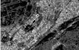
Figure 14.10 shows the result of applying the otb::LocalHoughImageFilter .
An interesting approach to feature extraction consists in computing the density of previously detected
features as simple edges or interest points.
The source code for this example can be found in the file
Examples/FeatureExtraction/EdgeDensityExample.cxx.
This example illustrates the use of the otb::EdgeDensityImageFilter . This filter computes a local
density of edges on an image and can be useful to detect man made objects or urban areas, for instance. The
filter has been implemented in a generic way, so that the way the edges are detected and the way their
density is computed can be chosen by the user.
The first step required to use this filter is to include its header file.
#include "otbEdgeDensityImageFilter.h"
We will also include the header files for the edge detector (a Canny filter) and the density estimation (a
simple count on a binary image).
The first step required to use this filter is to include its header file.
#include "itkCannyEdgeDetectionImageFilter.h" #include "otbBinaryImageDensityFunction.h"
As usual, we start by defining the types for the images, the reader and the writer.
typedef otb::Image<PixelType, Dimension> ImageType; typedef otb::ImageFileReader<ImageType> ReaderType;
typedef otb::ImageFileWriter<ImageType> WriterType;
We define now the type for the function which will be used by the edge density filter to estimate this
density. Here we choose a function which counts the number of non null pixels per area. The function takes
as template the type of the image to be processed.
typedef otb::BinaryImageDensityFunction<ImageType> CountFunctionType;
These non null pixels will be the result of an edge detector. We use here the classical Canny edge detector,
which is templated over the input and output image types.
typedef itk::CannyEdgeDetectionImageFilter<ImageType, ImageType> CannyDetectorType;
Finally, we can define the type for the edge density filter which takes as template the input and output image
types, the edge detector type, and the count function type..
typedef otb::EdgeDensityImageFilter<ImageType, ImageType, CannyDetectorType,
CountFunctionType> EdgeDensityFilterType;
We can now instantiate the different processing objects of the pipeline using the New() method.
ReaderType::Pointer reader = ReaderType::New();
EdgeDensityFilterType::Pointer filter = EdgeDensityFilterType::New();
CannyDetectorType::Pointer cannyFilter = CannyDetectorType::New();
WriterType::Pointer writer = WriterType::New();
The edge detection filter needs to be instantiated because we need to set its parameters. This is what we do
here for the Canny filter.
cannyFilter->SetUpperThreshold(upperThreshold); cannyFilter->SetLowerThreshold(lowerThreshold);
cannyFilter->SetVariance(variance); cannyFilter->SetMaximumError(maximumError);
After that, we can pass the edge detector to the filter which will be used it internally.
filter->SetDetector(cannyFilter); filter->SetNeighborhoodRadius(radius);
Finally, we set the file names for the input and the output images and we plug the pipeline. The Update()
method of the writer will trigger the processing.
reader->SetFileName(infname); writer->SetFileName(outfname);
filter->SetInput(reader->GetOutput()); writer->SetInput(filter->GetOutput()); writer->Update();
Figure 14.11 shows the result of applying the edge density filter to an image.
The complex geometric moments are defined as:
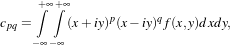 | (14.2) |
where x and y are the coordinates of the image f(x,y), i is the imaginary unit and p+q is the order of cpq.
The geometric moments are particularly useful in the case of scale changes.
The source code for this example can be found in the file
Examples/FeatureExtraction/ComplexMomentsImageFunctionExample.cxx.
This example illustrates the use of the otb::ComplexMomentsImageFunction .
The first step required to use this filter is to include its header file.
#include "otbComplexMomentsImageFunction.h"
The otb::ComplexMomentImageFunction is templated over the input image type and the output
complex type value, so we start by defining:
typedef otb::ComplexMomentsImageFunction<InputImageType> CMType;
typedef CMType::OutputType OutputType; CMType::Pointer cmFunction = CMType::New();
Next, we plug the input image into the complex moment function and we set its parameters.
reader->Update(); cmFunction->SetInputImage(reader->GetOutput()); cmFunction->SetQmax(Q);
cmFunction->SetPmax(P);
We can chose the pixel of the image which will used as center for the moment computation
InputImageType::IndexType center; center[0] = 50; center[1] = 50;
We can also choose the size of the neighborhood around the center pixel for the moment computation.
In order to get the value of the moment, we call the EvaluateAtIndex method.
OutputType Result = cmFunction->EvaluateAtIndex(center);
std::cout << "The moment of order (" << P << "," << Q << ") is equal to " << Result.at(P).at(Q) << std::endl;
The source code for this example can be found in the file
Examples/FeatureExtraction/ComplexMomentPathExample.cxx.
The complex moments can be computed on images, but sometimes we are interested in computing them on
shapes extracted from images by segmentation algorithms. These shapes can be represented by itk::Path
s. This example illustrates the use of the otb::ComplexMomentPathFunction for the computation of
complex geometric moments on ITK paths.
The first step required to use this filter is to include its header file.
#include "otbComplexMomentPathFunction.h"
The otb::ComplexMomentPathFunction is templated over the input path type and the output complex
type value, so we start by defining:
const unsigned int Dimension = 2; typedef itk::PolyLineParametricPath<Dimension> PathType;
typedef std::complex<double> ComplexType;
typedef otb::ComplexMomentPathFunction<PathType, ComplexType> CMType;
CMType::Pointer cmFunction = CMType::New();
Next, we set the parameters of the plug the input path into the complex moment function and we set its
parameters.
cmFunction->SetInputPath(path); cmFunction->SetQ(Q); cmFunction->SetP(P);
Since the paths are defined in physical coordinates, we do not need to set the center for the moment
computation as we did with the otb::ComplexMomentImageFunction . The same applies for the size of
the neighborhood around the center pixel for the moment computation. The moment computation is
triggered by calling the Evaluate method.
ComplexType Result = cmFunction->Evaluate(); std::cout << "The moment of order (" << P << "," << Q <<
") is equal to " << Result << std::endl;
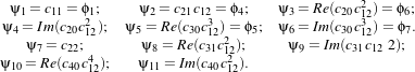
Using the algebraic moment theory, H. Ming-Kuel obtained a family of 7 invariants with respect to planar
transformations called Hu invariants, [60]. Those invariants can be seen as nonlinear combinations of the
complex moments. Hu invariants have been very much used in object recognition during the last 30
years, since they are invariant to rotation, scaling and translation. [46] gives their expressions
:
 | (14.3) |
[42] have used these invariants for the recognition of aircraft silhouettes. Flusser and Suk have used them
for image registration, [73].
The source code for this example can be found in the file
Examples/FeatureExtraction/HuMomentsImageFunctionExample.cxx.
This example illustrates the use of the otb::HuMomentsImageFunction .
The first step required to use this filter is to include its header file.
#include "otbHuMomentsImageFunction.h"
The otb::HuImageFunction is templated over the input image type and the output (real) type value, so
we start by defining:
typedef otb::HuMomentsImageFunction<InputImageType> HuType;
typedef HuType::OutputType MomentType; HuType::Pointer hmFunction = HuType::New();
We can choose the region and the pixel of the image which will used as coordinate origin for the moment
computation
InputImageType::RegionType region; InputImageType::SizeType size; InputImageType::IndexType start;
start[0] = 0; start[1] = 0; size[0] = 50; size[1] = 50; reader->Update();
InputImageType::Pointer image = reader->GetOutput(); region.SetIndex(start); region.SetSize(size);
image->SetRegions(region); image->Update(); InputImageType::IndexType center;
center[0] = start[0] + size[0] / 2; center[1] = start[1] + size[1] / 2;
Next, we plug the input image into the complex moment function and we set its parameters.
hmFunction->SetInputImage(image); hmFunction->SetNeighborhoodRadius(radius);
In order to get the value of the moment, we call the EvaluateAtIndex method.
MomentType Result = hmFunction->EvaluateAtIndex(center); for (unsigned int j=0; j<7; ++j) {
std::cout << "The moment of order " << j+1 << " is equal to " << Result[j] << std::endl; }
The following classes provide similar functionality:
The Hu invariants have been modified and improved by several authors. Flusser used these moments in
order to produce a new family of descriptors of order higher than 3, [46]. These descriptors are invariant to
scale and rotation. They have the following expressions:
 | (14.4) |
Examples
The source code for this example can be found in the file
Examples/FeatureExtraction/FlusserMomentsImageFunctionExample.cxx.
This example illustrates the use of the otb::FlusserMomentsImageFunction .
The first step required to use this filter is to include its header file.
#include "otbFlusserMomentsImageFunction.h"
The otb::FlusserMomentsImageFunction is templated over the input image type and the output (real)
type value, so we start by defining:
typedef otb::FlusserMomentsImageFunction<InputImageType> FlusserType;
typedef FlusserType::OutputType MomentType;
FlusserType::Pointer fmFunction = FlusserType::New();
We can choose the region and the pixel of the image which will used as coordinate origin for the moment
computation
InputImageType::RegionType region; InputImageType::SizeType size; InputImageType::IndexType start;
start[0] = 0; start[1] = 0; size[0] = 50; size[1] = 50; reader->Update();
InputImageType::Pointer image = reader->GetOutput(); region.SetIndex(start); region.SetSize(size);
image->SetRegions(region); image->Update(); InputImageType::IndexType center;
center[0] = start[0] + size[0] / 2; center[1] = start[1] + size[1] / 2;
Next, we plug the input image into the complex moment function and we set its parameters.
fmFunction->SetInputImage(image); fmFunction->SetNeighborhoodRadius(radius);
In order to get the value of the moment, we call the EvaluateAtIndex method.
MomentType Result = fmFunction->EvaluateAtIndex(center); for (unsigned int j=0; j<11; ++j) {
std::cout << "The moment of order " << j+1 << " is equal to " << Result[j] << std::endl; }
The following classes provide similar functionality:
Road extraction is a critical feature for an efficient use of high resolution satellite images. There are many
applications of road extraction: update of GIS database, reference for image registration, help for
identification algorithms and rapid mapping for example. Road network can be used to register an optical
image with a map or an optical image with a radar image for example. Road network extraction can help for
other algorithms: isolated building detection, bridge detection. In these cases, a rough extraction can be
sufficient. In the context of response to crisis, a fast mapping is necessary: within 6 hours, infrastructures
for the designated area are required. Within this timeframe, a manual extraction is inconceivable and an
automatic help is necessary.
The source code for this example can be found in the file
Examples/FeatureExtraction/ExtractRoadExample.cxx.
The easiest way to use the road extraction filter provided by OTB is to use the composite filter. If a
modification in the pipeline is required to adapt to a particular situation, the step by step example, described
in the next section can be adapted.
This example demonstrates the use of the otb::RoadExtractionFilter . This filter is a composite filter
achieving road extraction according to the algorithm adapted by E. Christophe and J. Inglada [24] from an
original method proposed in [84].
The first step toward the use of this filter is the inclusion of the proper header files.
#include "otbPolyLineParametricPathWithValue.h" #include "otbRoadExtractionFilter.h"
#include "otbDrawPathListFilter.h"
Then we must decide what pixel type to use for the image. We choose to do all the computation
in floating point precision and rescale the results between 0 and 255 in order to export PNG
images.
typedef double InputPixelType; typedef unsigned char OutputPixelType;
The images are defined using the pixel type and the dimension. Please note that the
otb::RoadExtractionFilter needs an otb::VectorImage as input to handle multispectral
images.
typedef otb::VectorImage<InputPixelType, Dimension> InputVectorImageType;
typedef otb::Image<InputPixelType, Dimension> InputImageType;
typedef otb::Image<OutputPixelType, Dimension> OutputImageType;
We define the type of the polyline that the filter produces. We use the otb::PolyLineParametricPathWithValue
, which allows the filter to produce a likehood value along with each polyline. The filter is able to produce
itk::PolyLineParametricPath as well.
typedef otb::PolyLineParametricPathWithValue<InputPixelType, Dimension> PathType;
Now we can define the otb::RoadExtractionFilter that takes a multi-spectral image as input and
produces a list of polylines.
typedef otb::RoadExtractionFilter<InputVectorImageType, PathType> RoadExtractionFilterType;
We also define an otb::DrawPathListFilter to draw the output polylines on an image, taking their
likehood values into account.
typedef otb::DrawPathListFilter<InputImageType, PathType, InputImageType> DrawPathFilterType;
The intensity rescaling of the results will be carried out by the itk::RescaleIntensityImageFilter
which is templated by the input and output image types.
typedef itk::RescaleIntensityImageFilter<InputImageType, OutputImageType> RescalerType;
An otb::ImageFileReader class is also instantiated in order to read image data from a
file. Then, an otb::ImageFileWriter is instantiated in order to write the output image to a
file.
typedef otb::ImageFileReader<InputVectorImageType> ReaderType;
typedef otb::ImageFileWriter<OutputImageType> WriterType;
The different filters composing our pipeline are created by invoking their New() methods, assigning the
results to smart pointers.
ReaderType::Pointer reader = ReaderType::New();
RoadExtractionFilterType::Pointer roadExtractionFilter = RoadExtractionFilterType::New();
DrawPathFilterType::Pointer drawingFilter = DrawPathFilterType::New();
RescalerType::Pointer rescaleFilter = RescalerType::New();
WriterType::Pointer writer = WriterType::New();
The otb::RoadExtractionFilter needs to have a reference pixel corresponding to the spectral content
likely to represent a road. This is done by passing a pixel to the filter. Here we suppose that the input image
has four spectral bands.
InputVectorImageType::PixelType ReferencePixel; ReferencePixel.SetSize(4);
ReferencePixel.SetElement(0, ::atof(argv[3])); ReferencePixel.SetElement(1, ::atof(argv[4]));
ReferencePixel.SetElement(2, ::atof(argv[5])); ReferencePixel.SetElement(3, ::atof(argv[6]));
roadExtractionFilter->SetReferencePixel(ReferencePixel);
We must also set the alpha parameter of the filter which allows us to tune the width of the roads we want to
extract. Typical value is 1.0 and should be working in most situations.
roadExtractionFilter->SetAlpha(atof(argv[7]));
All other parameter should not influence the results too much in most situation and can be kept at the
default value.
The amplitude threshold parameter tunes the sensitivity of the vectorization step. A typical value is
5⋅10-5.
roadExtractionFilter->SetAmplitudeThreshold(atof(argv[8]));
The tolerance threshold tunes the sensitivity of the path simplification step. Typical value is
1.0.
roadExtractionFilter->SetTolerance(atof(argv[9]));
Roads are not likely to have sharp turns. Therefore we set the max angle parameter, as well as the link
angular threshold. The value is typically  .
.
roadExtractionFilter->SetMaxAngle(atof(argv[10])); roadExtractionFilter->SetAngularThreshold(atof(argv[10]));
The otb::RoadExtractionFilter performs two odd path removing operations at different stage of its
execution. The first mean distance threshold and the second mean distance threshold set their criterion for
removal. Path are removed if their mean distance between nodes is to small, since such path coming from
previous filters are likely to be tortuous. The first removal operation as a typical mean distance threshold
parameter of 1.0, and the second of 10.0.
roadExtractionFilter->SetFirstMeanDistanceThreshold(atof(argv[11]));
roadExtractionFilter->SetSecondMeanDistanceThreshold(atof(argv[12]));
The otb::RoadExtractionFilter is able to link path whose ends are near according to an euclidean
distance criterion. The threshold for this distance to link a path is the distance threshold parameter. A
typical value is 25.
roadExtractionFilter->SetDistanceThreshold(atof(argv[13]));
We will now create a black background image to draw the resulting polyline on. To achieve this we need to
know the size of our input image. Therefore we trigger the GenerateOutputInformation() of the
reader.
reader->GenerateOutputInformation(); InputImageType::Pointer blackBackground = InputImageType::New();
blackBackground->CopyInformation(reader->GetOutput());
blackBackground->SetRegions(blackBackground->GetLargestPossibleRegion());
blackBackground->Allocate(); blackBackground->FillBuffer(0);
We tell the otb::DrawPathListFilter to try to use the likehood value embedded within the polyline as
a value for drawing this polyline if possible.
drawingFilter->UseInternalPathValueOn();
The itk::RescaleIntensityImageFilter needs to know which is the minimum and maximum values of
the output generated image. Those can be chosen in a generic way by using the NumericTraits functions,
since they are templated over the pixel type.
rescaleFilter->SetOutputMinimum(itk::NumericTraits<OutputPixelType>::min());
rescaleFilter->SetOutputMaximum(itk::NumericTraits<OutputPixelType>::max());
Now it is time for some pipeline wiring.
roadExtractionFilter->SetInput(reader->GetOutput()); drawingFilter->SetInput(blackBackground);
drawingFilter->SetInputPath(roadExtractionFilter->GetOutput());
rescaleFilter->SetInput(drawingFilter->GetOutput());
The update of the pipeline is triggered by the Update() method of the rescale intensity filter.
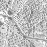
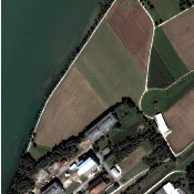
Figure 14.12 shows the result of applying the road extraction filter to a fusionned Quickbird image.
The source code for this example can be found in the file
Examples/FeatureExtraction/ExtractRoadByStepsExample.cxx.
This example illustrates the details of the otb::RoadExtractionFilter . This filter, described in the
previous section, is a composite filter that includes all the steps below. Individual filters can be replaced to
design a road detector targeted at SAR images for example.
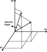
The spectral angle is used to compute a grayscale image from the multispectral original image using
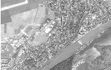
otb::SpectralAngleDistanceImageFilter . The spectral angle is illustrated on Figure 14.13. Pixels
corresponding to roads are in darker color.
typedef otb::SpectralAngleDistanceImageFilter<MultiSpectralImageType,
InternalImageType> SAFilterType; SAFilterType::Pointer saFilter = SAFilterType::New();
saFilter->SetReferencePixel(pixelRef); saFilter->SetInput(multispectralReader->GetOutput());
A square root is applied to the spectral angle image in order to enhance contrast between darker pixels
(which are pixels of interest) with itk::SqrtImageFilter .
typedef itk::SqrtImageFilter<InternalImageType, InternalImageType> SqrtFilterType;
SqrtFilterType::Pointer sqrtFilter = SqrtFilterType::New(); sqrtFilter->SetInput(saFilter->GetOutput());
Use the Gaussian gradient filter compute the gradient in x and y direction respectively (
itk::GradientRecursiveGaussianImageFilter ).
double sigma = alpha ⋆ (1.2 / resolution + 1);
typedef itk::GradientRecursiveGaussianImageFilter<InternalImageType, VectorImageType>
GradientFilterType; GradientFilterType::Pointer gradientFilter = GradientFilterType::New();
gradientFilter->SetSigma(sigma); gradientFilter->SetInput(sqrtFilter->GetOutput());
Compute the scalar product of the neighboring pixels and keep the minimum value and the direction
with otb::NeighborhoodScalarProductFilter . This is the line detector described in
[84].
typedef otb::NeighborhoodScalarProductFilter<VectorImageType, InternalImageType,
InternalImageType> NeighborhoodScalarProductType; NeighborhoodScalarProductType::Pointer scalarFilter
= NeighborhoodScalarProductType::New(); scalarFilter->SetInput(gradientFilter->GetOutput());
The resulting image is passed to the otb::RemoveIsolatedByDirectionFilter filter to remove pixels
with no neighbor having the same direction.
typedef otb::RemoveIsolatedByDirectionFilter<InternalImageType, InternalImageType, InternalImageType>
RemoveIsolatedByDirectionType; RemoveIsolatedByDirectionType::Pointer removeIsolatedByDirectionFilter
= RemoveIsolatedByDirectionType::New(); removeIsolatedByDirectionFilter->SetInput(scalarFilter->GetOutput());
removeIsolatedByDirectionFilter ->SetInputDirection(scalarFilter->GetOutputDirection());
We remove pixels having a direction corresponding to bright lines as we know that after the spectral angle,
roads are in darker color with the otb::RemoveWrongDirectionFilter filter.
typedef otb::RemoveWrongDirectionFilter<InternalImageType,
InternalImageType, InternalImageType> RemoveWrongDirectionType;
RemoveWrongDirectionType::Pointer removeWrongDirectionFilter = RemoveWrongDirectionType::New();
removeWrongDirectionFilter->SetInput( removeIsolatedByDirectionFilter->GetOutput());
removeWrongDirectionFilter->SetInputDirection( scalarFilter->GetOutputDirection());
We remove pixels which are not maximum on the direction perpendicular to the road direction with the
otb::NonMaxRemovalByDirectionFilter .
typedef otb::NonMaxRemovalByDirectionFilter<InternalImageType,
InternalImageType, InternalImageType> NonMaxRemovalByDirectionType;
NonMaxRemovalByDirectionType::Pointer nonMaxRemovalByDirectionFilter = NonMaxRemovalByDirectionType::New();
nonMaxRemovalByDirectionFilter->SetInput( removeWrongDirectionFilter->GetOutput());
nonMaxRemovalByDirectionFilter ->SetInputDirection(scalarFilter->GetOutputDirection());
Extracted road are vectorized into polylines with otb::VectorizationPathListFilter
.
typedef otb::VectorizationPathListFilter<InternalImageType, InternalImageType,
PathType> VectorizationFilterType; VectorizationFilterType::Pointer vectorizationFilter
= VectorizationFilterType::New(); vectorizationFilter->SetInput(nonMaxRemovalByDirectionFilter->GetOutput());
vectorizationFilter->SetInputDirection(scalarFilter->GetOutputDirection());
vectorizationFilter->SetAmplitudeThreshold(atof(argv[8]));
However, this vectorization is too simple and need to be refined to be usable. First, we remove all aligned
points to make one segment with otb::SimplifyPathListFilter . Then we break the polylines which
have sharp angles as they are probably not road with otb::BreakAngularPathListFilter .
Finally we remove path which are too short with otb::RemoveTortuousPathListFilter
.
typedef otb::SimplifyPathListFilter<PathType> SimplifyPathType;
SimplifyPathType::Pointer simplifyPathListFilter = SimplifyPathType::New();
simplifyPathListFilter->GetFunctor().SetTolerance(1.0);
simplifyPathListFilter->SetInput(vectorizationFilter->GetOutput());
typedef otb::BreakAngularPathListFilter<PathType> BreakAngularPathType;
BreakAngularPathType::Pointer breakAngularPathListFilter = BreakAngularPathType::New();
breakAngularPathListFilter->SetMaxAngle(otb::CONST_PI / 8.);
breakAngularPathListFilter->SetInput(simplifyPathListFilter->GetOutput());
typedef otb::RemoveTortuousPathListFilter<PathType> RemoveTortuousPathType;
RemoveTortuousPathType::Pointer removeTortuousPathListFilter = RemoveTortuousPathType::New();
removeTortuousPathListFilter->GetFunctor().SetThreshold(1.0);
removeTortuousPathListFilter->SetInput(breakAngularPathListFilter->GetOutput());
Polylines within a certain range are linked ( otb::LinkPathListFilter ) to try to fill gaps due to
occultations by vehicules, trees, etc. before simplifying polylines ( otb::SimplifyPathListFilter ) and
removing the shortest ones with otb::RemoveTortuousPathListFilter .
typedef otb::LinkPathListFilter<PathType> LinkPathType;
LinkPathType::Pointer linkPathListFilter = LinkPathType::New();
linkPathListFilter->SetDistanceThreshold(25.0 / resolution);
linkPathListFilter->SetAngularThreshold(otb::CONST_PI / 8);
linkPathListFilter->SetInput(removeTortuousPathListFilter->GetOutput());
SimplifyPathType::Pointer simplifyPathListFilter2 = SimplifyPathType::New();
simplifyPathListFilter2->GetFunctor().SetTolerance(1.0);
simplifyPathListFilter2->SetInput(linkPathListFilter->GetOutput());
RemoveTortuousPathType::Pointer removeTortuousPathListFilter2 = RemoveTortuousPathType::New();
removeTortuousPathListFilter2->GetFunctor().SetThreshold(10.0);
removeTortuousPathListFilter2->SetInput(simplifyPathListFilter2->GetOutput());
A value can be associated with each polyline according to pixel values under the polyline with
otb::LikelihoodPathListFilter . A higher value will mean a higher Likelihood to be a
road.
typedef otb::LikelihoodPathListFilter<PathType, InternalImageType> PathListToPathListWithValueType;
PathListToPathListWithValueType::Pointer pathListConverter = PathListToPathListWithValueType::New();
pathListConverter->SetInput(removeTortuousPathListFilter2->GetOutput());
pathListConverter->SetInputImage(nonMaxRemovalByDirectionFilter->GetOutput());
A black background image is built to draw the path on.
InternalImageType::Pointer output = InternalImageType::New();
output->CopyInformation(multispectralReader->GetOutput());
output->SetRegions(output->GetLargestPossibleRegion()); output->Allocate(); output->FillBuffer(0.0);
Polylines are drawn on a black background image with otb::DrawPathListFilter . The
SetUseIternalValues() tell the drawing filter to draw the path with its Likelihood value.
typedef otb::DrawPathListFilter<InternalImageType, PathType, InternalImageType> DrawPathType;
DrawPathType::Pointer drawPathListFilter = DrawPathType::New(); drawPathListFilter->SetInput(output);
drawPathListFilter->SetInputPath(pathListConverter->GetOutput());
drawPathListFilter->SetUseInternalPathValue(true);
The output from the drawing filter contains very small values (Likelihood values). Therefore the image has
to be rescaled to be viewed. The whole pipeline is executed by invoking the Update() method on this last
filter.
typedef itk::RescaleIntensityImageFilter<InternalImageType, InternalImageType> RescalerType;
RescalerType::Pointer rescaler = RescalerType::New(); rescaler->SetOutputMaximum(255);
rescaler->SetOutputMinimum(0); rescaler->SetInput(drawPathListFilter->GetOutput()); rescaler->Update();
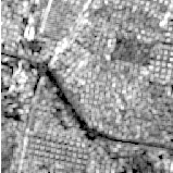
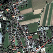
Figures 14.14 and 14.15 show the result of applying the road extraction by steps to a fusionned Quickbird
image. The result image is a RGB composition showing the extracted path in red. Full processing took
about 3 seconds for each image.
The source code for this example can be found in the file
Examples/FeatureExtraction/CloudDetectionExample.cxx.
The cloud detection functor is a processing chain composed by the computation of a spectral angle (with
SpectralAngleFunctor). The result is multiplied by a gaussian factor (with CloudEstimatorFunctor) and
finally thresholded to obtain a binary image (with CloudDetectionFilter). However, modifications can be
added in the pipeline to adapt to a particular situation.
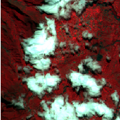
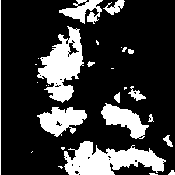
This example demonstrates the use of the otb::CloudDetectionFilter . This filter uses the spectral
angle principle to measure the radiometric gap between a reference pixel and the other pixels of the
image.
The first step toward the use of this filter is the inclusion of the proper header files.
#include "otbCloudDetectionFilter.h"
Then we must decide what pixel type to use for the images. We choose to do all the computations in double
precision.
typedef double InputPixelType; typedef double OutputPixelType;
The images are defined using the pixel type and the dimension. Please note that the
otb::CloudDetectionFilter needs an otb::VectorImage as input to handle multispectral
images.
typedef otb::VectorImage<InputPixelType, Dimension> VectorImageType;
typedef VectorImageType::PixelType VectorPixelType;
typedef otb::Image<OutputPixelType, Dimension> OutputImageType;
We define the functor type that the filter will use. We use the otb::CloudDetectionFunctor
.
typedef otb::Functor::CloudDetectionFunctor<VectorPixelType, OutputPixelType> FunctorType;
Now we can define the otb::CloudDetectionFilter that takes a multi-spectral image as input and
produces a binary image.
typedef otb::CloudDetectionFilter<VectorImageType, OutputImageType, FunctorType> CloudDetectionFilterType;
An otb::ImageFileReader class is also instantiated in order to read image data from a
file. Then, an otb::ImageFileWriter is instantiated in order to write the output image to a
file.
typedef otb::ImageFileReader<VectorImageType> ReaderType;
typedef otb::ImageFileWriter<OutputImageType> WriterType;
The different filters composing our pipeline are created by invoking their New() methods, assigning the
results to smart pointers.
ReaderType::Pointer reader = ReaderType::New(); CloudDetectionFilterType::Pointer cloudDetection =
CloudDetectionFilterType::New(); WriterType::Pointer writer = WriterType::New();
The otb::CloudDetectionFilter needs to have a reference pixel corresponding to the spectral content
likely to represent a cloud. This is done by passing a pixel to the filter. Here we suppose that the input image
has four spectral bands.
VectorPixelType referencePixel; referencePixel.SetSize(4); referencePixel.Fill(0.);
referencePixel[0] = (atof(argv[5])); referencePixel[1] = (atof(argv[6])); referencePixel[2] = (atof(argv[7]));
referencePixel[3] = (atof(argv[8])); cloudDetection->SetReferencePixel(referencePixel);
We must also set the variance parameter of the filter and the parameter of the gaussian functor. The bigger
the value, the more tolerant the detector will be.
cloudDetection->SetVariance(atof(argv[9]));
The minimum and maximum thresholds are set to binarise the final result. These values have to be between
0 and 1.
cloudDetection->SetMinThreshold(atof(argv[10])); cloudDetection->SetMaxThreshold(atof(argv[11]));
writer->SetFileName(argv[2]); writer->SetInput(cloudDetection->GetOutput()); writer->Update();
Figure 14.16 shows the result of applying the cloud detection filter to a cloudy image.