Remote sensing is not just a matter of taking pictures, but also – mostly – a matter of measuring
physical values. In order to properly deal with physical magnitudes, the numerical values provided
by the sensors have to be calibrated. After that, several indices with physical meaning can be
computed.
With multispectral sensors, several indices can be computed, combining several spectral bands to show
features that are not obvious using only one band. Indices can show:
- Vegetation (Tab 12.1)
- Soil (Tab 12.2)
- Water (Tab 12.3)
- Built up areas (Tab 12.4)
A vegetation index is a quantitative measure used to measure biomass or vegetative vigor, usually formed
from combinations of several spectral bands, whose values are added, divided, or multiplied in order to
yield a single value that indicates the amount or vigor of vegetation.
Numerous indices are available in OTB and are listed in table 12.1 to 12.4 with their references.
|
|
| NDVI | Normalized Difference Vegetation Index [119] |
| RVI | Ratio Vegetation Index [103] |
| PVI | Perpendicular Vegetation Index [116, 144] |
| SAVI | Soil Adjusted Vegetation Index [64] |
| TSAVI | Transformed Soil Adjusted Vegetation Index [9, 8] |
| MSAVI | Modified Soil Adjusted Vegetation Index [112] |
| MSAVI2 | Modified Soil Adjusted Vegetation Index [112] |
| GEMI | Global Environment Monitoring Index [108] |
| WDVI | Weighted Difference Vegetation Index [26, 27] |
| AVI | Angular Vegetation Index [110] |
| ARVI | Atmospherically Resistant Vegetation Index [79] |
| TSARVI | Transformed Soil Adjusted Vegetation Index [79] |
| EVI | Enhanced Vegetation Index [65, 76] |
| IPVI | Infrared Percentage Vegetation Index [31] |
| TNDVI | Transformed NDVI [35] |
|
|
| |
Table 12.1: Vegetation indices
|
|
| IR | Redness Index [45] |
| IC | Color Index [45] |
| IB | Brilliance Index [98] |
| IB2 | Brilliance Index [98] |
|
|
| |
Table 12.2: Soil indices
|
|
| SRWI | Simple Ratio Water Index [150] |
| NDWI | Normalized Difference Water Index [20] |
| NDWI2 | Normalized Difference Water Index [95] |
| MNDWI | Modified Normalized Difference Water Index [146] |
| NDPI | Normalized Difference Pond Index [83] |
| NDTI | Normalized Difference Turbidity Index [83] |
| SA | Spectral Angle |
|
|
| |
Table 12.3: Water indices
|
|
| NDBI | Normalized Difference Built Up Index [97] |
| ISU | Index Surfaces Built [1] |
|
|
| |
Table 12.4: Built-up indices
The use of the different indices is very similar, and only few example are given in the next
sections.
NDVI was one of the most successful of many attempts to simply and quickly identify vegetated areas and
their condition, and it remains the most well-known and used index to detect live green plant canopies in
multispectral remote sensing data. Once the feasibility to detect vegetation had been demonstrated, users
tended to also use the NDVI to quantify the photosynthetic capacity of plant canopies. This, however, can
be a rather more complex undertaking if not done properly.
The source code for this example can be found in the file
Examples/Radiometry/NDVIRAndNIRVegetationIndexImageFilter.cxx.
The following example illustrates the use of the otb::RAndNIRIndexImageFilter with the use of the
Normalized Difference Vegatation Index (NDVI). NDVI computes the difference between the NIR channel,
noted LNIR, and the red channel, noted Lr radiances reflected from the surface and transmitted through the
atmosphere:
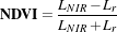 | (12.1) |
The following classes provide similar functionality:
With the otb::RAndNIRIndexImageFilter class the filter inputs are one channel images: one inmage
represents the NIR channel, the the other the NIR channel.
Let’s look at the minimal code required to use this algorithm. First, the following header defining the
otb::RAndNIRIndexImageFilter class must be included.
#include "otbRAndNIRIndexImageFilter.h"
The image types are now defined using pixel types the dimension. Input and output images are defined as
otb::Image .
const unsigned int Dimension = 2; typedef double InputPixelType;
typedef float OutputPixelType;
typedef otb::Image<InputPixelType, Dimension> InputRImageType;
typedef otb::Image<InputPixelType, Dimension> InputNIRImageType;
typedef otb::Image<OutputPixelType, Dimension> OutputImageType;
The NDVI (Normalized Difference Vegetation Index) is instantiated using the images pixel type as
template parameters. It is implemented as a functor class which will be passed as a parameter to an
otb::RAndNIRIndexImageFilter .
typedef otb::Functor::NDVI<InputPixelType, InputPixelType, OutputPixelType> FunctorType;
The otb::RAndNIRIndexImageFilter type is instantiated using the images types and the NDVI functor
as template parameters.
typedef otb::RAndNIRIndexImageFilter<InputRImageType, InputNIRImageType,
OutputImageType, FunctorType> RAndNIRIndexImageFilterType;
Now the input images are set and a name is given to the output image.
readerR->SetFileName(argv[1]); readerNIR->SetFileName(argv[2]); writer->SetFileName(argv[3]);
We set the processing pipeline: filter inputs are linked to the reader output and the filter output is linked to
the writer input.
filter->SetInputR(readerR->GetOutput()); filter->SetInputNIR(readerNIR->GetOutput());
writer->SetInput(filter->GetOutput());
Invocation of the Update() method on the writer triggers the execution of the pipeline. It is
recommended to place update() calls in a try/catch block in case errors occur and exceptions are
thrown.
try { writer->Update(); } catch (itk::ExceptionObject& excep) {
std::cerr << "Exception caught !" << std::endl; std::cerr << excep << std::endl; }
Let’s now run this example using as input the images NDVI_3.hdr and NDVI_4.hdr (images kindly and free
of charge given by SISA and CNES) provided in the directory Examples/Data.
The source code for this example can be found in the file
Examples/Radiometry/ARVIMultiChannelRAndBAndNIRVegetationIndexImageFilter.cxx.
The following example illustrates the use of the otb::MultiChannelRAndBAndNIRIndexImageFilter
with the use of the Atmospherically Resistant Vegetation Index (ARVI) otb::Functor::ARVI . ARVI is
an improved version of the NDVI that is more robust to the atmospheric effect. In addition to the red and
NIR channels (used in the NDVI), the ARVI takes advantage of the presence of the blue channel to
accomplish a self-correction process for the atmospheric effect on the red channel. For this, it uses the
difference in the radiance between the blue and the red channels to correct the radiance in the
red channel. Let’s define ρNIR*, ρr*, ρb* the normalized radiances (that is to say the radiance
normalized to reflectance units) of red, blue and NIR channels respectively. ρrb* is defined
as
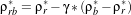 | (12.2) |
The ARVI expression is
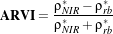 | (12.3) |
This formula can be simplified with :
 | (12.4) |
For more details, refer to Kaufman and Tanre’ work [79].
The following classes provide similar functionality:
With the otb::MultiChannelRAndBAndNIRIndexImageFilter class the input has to be a multi channel
image and the user has to specify index channel of the red, blue and NIR channel.
Let’s look at the minimal code required to use this algorithm. First, the following header defining the
otb::MultiChannelRAndBAndNIRIndexImageFilter class must be included.
#include "otbMultiChannelRAndBAndNIRIndexImageFilter.h"
The image types are now defined using pixel types and dimension. The input image is defined as an
otb::VectorImage , the output is a otb::Image .
const unsigned int Dimension = 2; typedef double InputPixelType;
typedef float OutputPixelType;
typedef otb::VectorImage<InputPixelType, Dimension> InputImageType;
typedef otb::Image<OutputPixelType, Dimension> OutputImageType;
The ARVI (Atmospherically Resistant Vegetation Index) is instantiated using the image pixel types as
template parameters. Note that we also can use other functors which operate with the Red, Blue and Nir
channels such as EVI, ARVI and TSARVI.
typedef otb::Functor::ARVI<InputPixelType, InputPixelType, InputPixelType,
OutputPixelType> FunctorType;
The otb::MultiChannelRAndBAndNIRIndexImageFilter type is defined using the image types and the
ARVI functor as template parameters. We then instantiate the filter itself.
typedef otb::MultiChannelRAndBAndNIRIndexImageFilter <InputImageType, OutputImageType, FunctorType>
MultiChannelRAndBAndNIRIndexImageFilterType; MultiChannelRAndBAndNIRIndexImageFilterType::Pointer
filter = MultiChannelRAndBAndNIRIndexImageFilterType::New();
Now the input image is set and a name is given to the output image.
reader->SetFileName(argv[1]); writer->SetFileName(argv[2]);
The three used index bands (red, blue and NIR) are declared.
filter->SetRedIndex(::atoi(argv[5])); filter->SetBlueIndex(::atoi(argv[6]));
filter->SetNIRIndex(::atoi(argv[7]));
The γ parameter is set. The otb::MultiChannelRAndBAndNIRIndexImageFilter class sets the
default value of γ to 0.5. This parameter is used to reduce the atmospheric effect on a global
scale.
filter->GetFunctor().SetGamma(::atof(argv[8]));
The filter input is linked to the reader output and the filter output is linked to the writer input.
filter->SetInput(reader->GetOutput()); writer->SetInput(filter->GetOutput());
The invocation of the Update() method on the writer triggers the execution of the pipeline. It is
recommended to place update calls in a try/catch block in case errors occur and exceptions are
thrown.
try { writer->Update(); } catch (itk::ExceptionObject& excep) {
std::cerr << "Exception caught !" << std::endl; std::cerr << excep << std::endl; }
Let’s now run this example using as input the image IndexVegetation.hd (image kindly and free of
charge given by SISA and CNES) and γ=0.6 provided in the directory Examples/Data.
12.1.4 AVI
The source code for this example can be found in the file
Examples/Radiometry/AVIMultiChannelRAndGAndNIRVegetationIndexImageFilter.cxx.
The following example illustrates the use of the otb::MultiChannelRAndGAndNIR VegetationIndexImageFilter
with the use of the Angular Vegetation Index (AVI). The equation for the Angular Vegetation Index involves
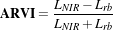
the gren, red and near infra-red bands. λ1, λ2 and λ3 are the mid-band wavelengths for the green, red and
NIR bands and tan-1 is the arctangent function.
The AVI expression is
 | (12.5) |
 | (12.6) |
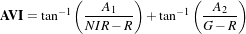 | (12.7) |
For more details, refer to Plummer work [110].
With the otb::MultiChannelRAndGAndNIRIndexImageFilter class the input has to be a
multi channel image and the user has to specify the channel index of the red, green and NIR
channel.
Let’s look at the minimal code required to use this algorithm. First, the following header defining the
otb::MultiChannelRAndGAndNIRIndexImageFilter class must be included.
#include "otbMultiChannelRAndGAndNIRIndexImageFilter.h"
The image types are now defined using pixel types and dimension. The input image is defined as an
otb::VectorImage , the output is a otb::Image .
const unsigned int Dimension = 2; typedef double InputPixelType;
typedef float OutputPixelType;
typedef otb::VectorImage<InputPixelType, Dimension> InputImageType;
typedef otb::Image<OutputPixelType, Dimension> OutputImageType;
The AVI (Angular Vegetation Index) is instantiated using the image pixel types as template
parameters.
typedef otb::Functor::AVI<InputPixelType, InputPixelType, InputPixelType, OutputPixelType> FunctorType;
The otb::MultiChannelRAndGAndNIRIndexImageFilter type is defined using the image types and the
AVI functor as template parameters. We then instantiate the filter itself.
typedef otb::MultiChannelRAndGAndNIRIndexImageFilter <InputImageType, OutputImageType, FunctorType>
MultiChannelRAndGAndNIRIndexImageFilterType; MultiChannelRAndGAndNIRIndexImageFilterType::Pointer
filter = MultiChannelRAndGAndNIRIndexImageFilterType::New();
Now the input image is set and a name is given to the output image.
reader->SetFileName(argv[1]); writer->SetFileName(argv[2]);
The three used index bands (red, green and NIR) are declared.
filter->SetRedIndex(::atoi(argv[5])); filter->SetGreenIndex(::atoi(argv[6]));
filter->SetNIRIndex(::atoi(argv[7]));
The λ R, G and NIR parameters are set. The otb::MultiChannelRAndGAndNIRIndexImageFilter
class sets the default values of λ to 660, 560 and 830.
filter->GetFunctor().SetLambdaR(::atof(argv[8])); filter->GetFunctor().SetLambdaG(::atof(argv[9]));
filter->GetFunctor().SetLambdaNir(::atof(argv[10]));
The filter input is linked to the reader output and the filter output is linked to the writer input.
filter->SetInput(reader->GetOutput()); writer->SetInput(filter->GetOutput());
The invocation of the Update() method on the writer triggers the execution of the pipeline. It is
recommended to place update calls in a try/catch block in case errors occur and exceptions are
thrown.
try { writer->Update(); } catch (itk::ExceptionObject& excep) {
std::cerr << "Exception caught !" << std::endl; std::cerr << excep << std::endl; }
Let’s now run this example using as input the image verySmallFSATSW.tif provided in the directory
Examples/Data.
The source code for this example can be found in the file
Examples/Radiometry/AtmosphericCorrectionSequencement.cxx.
The following example illustrates the application of atmospheric corrections to an optical multispectral
image similar to Pleiades. These corrections are made in four steps :
- digital number to radiance correction;
- radiance to refletance image conversion;
- atmospheric correction for TOA (top of atmosphere) to TOC (top of canopy) reflectance
estimation;
- correction of the adjacency effects taking into account the neighborhood contribution.
The manipulation of each class used for the different steps and the link with the 6S radiometry library will
be explained. In particular, the API modifications that have been made in version 4.2 will be detailed. There
was several reasons behind these modifications :
- fix design issues in the framework that were causing trouble when setting the atmospheric
parameters
- allow the computation of the radiative terms by other libraries than 6S (such as SMAC
method).
- allow the users of the OpticalCalibration application to set and override each correction
parameter.
Let’s look at the minimal code required to use this algorithm. First, the following header defining the
otb::AtmosphericCorrectionSequencement class must be included. For the numerical to radiance
image, radiance to refletance image, and reflectance to atmospheric correction image corrections and the
neighborhood correction, four header files are required.
#include "otbImageToRadianceImageFilter.h" #include "otbRadianceToReflectanceImageFilter.h"
#include "otbReflectanceToSurfaceReflectanceImageFilter.h"
#include "otbSurfaceAdjacencyEffectCorrectionSchemeFilter.h"
In version 4.2, the class SurfaceAdjacencyEffect6SCorrectionSchemeFilter has been renamed
into otb::SurfaceAdjacencyEffectCorrectionSchemeFilter , but it still does the same
thing.
This chain uses the 6S radiative transfer code to compute radiative terms (for instance upward and
downward transmittance). The inputs needed are separated into two categories :
- The atmospheric correction parameters : physical parameters of the
atmosphere when the image was taken (for instance : atmospheric pressure,
water vapour amount, aerosol data, ...). They are stored in the class
otb::AtmosphericCorrectionParameters .
- The acquisition correction parameters : sensor related information about the way the image
was taken, usually available with the image metadata (for instance : solar angles, spectral
sensitivity, ...). They are stored in the class otb::ImageMetadataCorrectionParameters
.
The class otb::RadiometryCorrectionParametersToAtmisphericRadiativeTerms computes the
radiative terms using these two types of parameters. It contains a single static method that calls the 6S
library. The header also includes the classes to manipulate correction parameters and radiative terms.
Image types are now defined using pixel types and dimension. The input image is defined as an
otb::VectorImage , the output image is a otb::VectorImage . To simplify, input and output image
types are the same one.
const unsigned int Dimension = 2; typedef double PixelType;
typedef otb::VectorImage<PixelType, Dimension> ImageType;
The GenerateOutputInformation() reader method is called to know the number of component per pixel
of the image. It is recommended to place GenerateOutputInformation calls in a try/catch block in
case errors occur and exceptions are thrown.
reader->SetFileName(argv[1]); try { reader->GenerateOutputInformation(); }
catch (itk::ExceptionObject& excep) { std::cerr << "Exception caught !" << std::endl;
std::cerr << excep << std::endl; }
The otb::ImageToRadianceImageFilter type is defined and instancied. This class uses a functor
applied to each component of each pixel (Xk) whose formula is:
 | (12.8) |
Where :
- LTOAk is the incident radiance (in W.m-2.sr-1.μm-1);
- Xk is the measured digital number (ie. the input image pixel component);
- αk is the absolute calibration gain for the channel k;
- βk is the absolute calibration bias for the channel k.
typedef otb::ImageToRadianceImageFilter<ImageType, ImageType> ImageToRadianceImageFilterType;
ImageToRadianceImageFilterType::Pointer filterImageToRadiance = ImageToRadianceImageFilterType::New();
Here, α and β are read from an ASCII file given in input, stored in a vector and passed to the class.
filterImageToRadiance->SetAlpha(alpha); filterImageToRadiance->SetBeta(beta);
The otb::RadianceToReflectanceImageFilter type is defined and instancied. This class used a
functor applied to each component of each pixel of the radiance filter output (LTOAk):
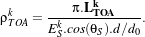 | (12.9) |
Where :
- ρTOAk is the reflectance measured by the sensor;
- θS is the zenithal solar angle in degrees;
- ESk is the solar illumination out of the atmosphere measured at a distance d0 from the Earth;
- d∕d0 is the ratio between the Earth-Sun distance at the acquisition date and the mean
Earth-Sun distance. The ratio can be directly given to the class or computed using a 6S routine.
TODO In the last case (that is the one of this example), the user has to precise the month and
the day of the acquisition.
typedef otb::RadianceToReflectanceImageFilter<ImageType, ImageType> RadianceToReflectanceImageFilterType;
RadianceToReflectanceImageFilterType::Pointer filterRadianceToReflectance
= RadianceToReflectanceImageFilterType::New();
The solar illumination is read from a ASCII file given in input, stored in a vector and given to
the class. Day, month and zenital solar angle are inputs and can be directly given to the class.
filterRadianceToReflectance->SetZenithalSolarAngle( static_cast<double>(atof(argv[6])));
filterRadianceToReflectance->SetDay(atoi(argv[7])); filterRadianceToReflectance->SetMonth(atoi(argv[8]));
filterRadianceToReflectance->SetSolarIllumination(solarIllumination);
At this step of the chain, radiative information are nedeed to compute the contribution of the atmosphere
(such as atmosphere transmittance and reflectance). Those information will be computed from
different correction parameters stored in otb::AtmosphericCorrectionParameters and
otb::ImageMetadataCorrectionParameters instances. These containers will be given to the static
function Compute from otb::RadiometryCorrectionParametersToAtmosphericRadiativeTerms
class, which will call a 6S routine that will compute the needed radiometric information
and store them in a otb::AtmosphericRadiativeTerms class instance. For this,
otb::RadiometryCorrectionParametersToAtmosphericRadiativeTerms ,
otb::AtmosphericCorrectionParameters , otb::ImageMetadataCorrectionParameters and
otb::AtmosphericRadiativeTerms types are defined and instancied.
typedef otb::RadiometryCorrectionParametersToAtmosphericRadiativeTerms
RadiometryCorrectionParametersToRadiativeTermsType; typedef otb::AtmosphericCorrectionParameters
AtmosphericCorrectionParametersType; typedef otb::ImageMetadataCorrectionParameters
AcquisitionCorrectionParametersType; typedef otb::AtmosphericRadiativeTerms AtmosphericRadiativeTermsType;
The otb::ImageMetadataCorrectionParameters class stores several parameters that are generally
present in the image metadata :
- The zenithal and azimutal solar angles that describe the solar incidence configuration (in
degrees);
- The zenithal and azimuthal viewing angles that describe the viewing direction (in degrees);
- The month and the day of the acquisition;
- The filter function that is the values of the filter function for one spectral band, from λinf to
λsup by step of 2.5 nm. One filter function by channel is required. This last parameter are read
in text files, the other one are directly given to the class.
When this container is not set in the ReflectanceToSurfaceReflectance filter, it is automatically filled
using the image metadata. The following lines show that it is also possible to set the values
manually.
dataAcquisitionCorrectionParameters->SetSolarZenithalAngle( static_cast<double>(atof(argv[6])));
dataAcquisitionCorrectionParameters->SetSolarAzimutalAngle( static_cast<double>(atof(argv[9])));
dataAcquisitionCorrectionParameters->SetViewingZenithalAngle( static_cast<double>(atof(argv[10])));
dataAcquisitionCorrectionParameters->SetViewingAzimutalAngle( static_cast<double>(atof(argv[11])));
dataAcquisitionCorrectionParameters->SetMonth(atoi(argv[8]));
dataAcquisitionCorrectionParameters->SetDay(atoi(argv[7]));
The otb::AtmosphericCorrectionParameters class stores physical parameters of the atmosphere that
are not impacted by the viewing angles of the image :
- The atmospheric pressure;
- The water vapor amount, that is, the total water vapor content over vertical atmospheric
column;
- The ozone amount that is the Stratospheric ozone layer content;
- The aerosol model that is the kind of particles (no aerosol, continental, maritime, urban,
desertic);
- The aerosol optical thickness at 550 nm that is the is the Radiative impact of aerosol for the
reference wavelength 550 nm;
dataAtmosphericCorrectionParameters->SetAtmosphericPressure( static_cast<double>(atof(argv[12])));
dataAtmosphericCorrectionParameters->SetWaterVaporAmount( static_cast<double>(atof(argv[13])));
dataAtmosphericCorrectionParameters->SetOzoneAmount( static_cast<double>(atof(argv[14])));
AerosolModelType aerosolModel = static_cast<AerosolModelType>(::atoi(argv[15]));
dataAtmosphericCorrectionParameters->SetAerosolModel(aerosolModel);
dataAtmosphericCorrectionParameters->SetAerosolOptical( static_cast<double>(atof(argv[16])));
Once those parameters are loaded, they are used by the 6S library to compute the needed radiometric information.
The RadiometryCorrectionParametersToAtmosphericRadiativeTerms class provides a static function to perform
this step .
AtmosphericRadiativeTermsType::Pointer atmosphericRadiativeTerms =
RadiometryCorrectionParametersToRadiativeTermsType::Compute(
dataAtmosphericCorrectionParameters, dataAcquisitionCorrectionParameters);
The output is stored inside an instance of the otb::AtmosphericRadiativeTerms class. This class
contains (for each channel of the image)
- The Intrinsic atmospheric reflectance that takes into account for the molecular scattering and
the aerosol scattering attenuated by water vapor absorption;
- The spherical albedo of the atmosphere;
- The total gaseous transmission (for all species);
- The total transmittance of the atmosphere from sun to ground (downward transmittance) and
from ground to space sensor (upward transmittance).
Atmospheric corrections can now start. First, an instance of otb::ReflectanceToSurfaceReflectanceImageFilter
is created.
typedef otb::ReflectanceToSurfaceReflectanceImageFilter<ImageType, ImageType>
ReflectanceToSurfaceReflectanceImageFilterType; ReflectanceToSurfaceReflectanceImageFilterType::Pointer
filterReflectanceToSurfaceReflectanceImageFilter = ReflectanceToSurfaceReflectanceImageFilterType::New();
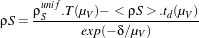
The aim of the atmospheric correction is to invert the surface reflectance (for each pixel of the input
image) from the TOA reflectance and from simulations of the atmospheric radiative functions
corresponding to the geometrical conditions of the observation and to the atmospheric components. The
process required to be applied on each pixel of the image, band by band with the following
formula:
 | (12.10) |
Where,
 | (12.11) |
With :
- ρTOA is the reflectance at the top of the atmosphere;
- ρSunif is the ground reflectance under assumption of a lambertian surface and an uniform
environment;
- ρatm is the intrinsic atmospheric reflectance;
- tgallgas is the spherical albedo of the atmosphere;
- T (μS) is the downward transmittance;
- T (μV ) is the upward transmittance.
All those parameters are contained in the AtmosphericRadiativeTerms container.
filterReflectanceToSurfaceReflectanceImageFilter-> SetAtmosphericRadiativeTerms(atmosphericRadiativeTerms);
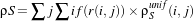
Next (and last step) is the neighborhood correction. For this, the SurfaceAdjacencyEffectCorrectionSchemeFilter
class is used. The previous surface reflectance inversion is performed under the assumption
of a homogeneous ground environment. The following step allows correcting the adjacency
effect on the radiometry of pixels. The method is based on the decomposition of the observed
signal as the summation of the own contribution of the target pixel and of the contributions of
neighbored pixels moderated by their distance to the target pixel. A simplified relation may be
:
 | (12.12) |
With :
- ρSunif is the ground reflectance under assumption of an homogeneous environment;
- T (μV ) is the upward transmittance;
- td(μS) is the upward diffus transmittance;
- exp(-δ∕μV ) is the upward direct transmittance;
- ρS is the environment contribution to the pixel target reflectance in the total observed
signal.
 | (12.13) |
where,
- r(i, j) is the distance between the pixel(i, j) and the central pixel of the window in km;
- f(r) is the global environment function.
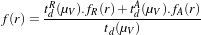 | (12.14) |
The neighborhood consideration window size is given by the window radius.
An instance of otb::SurfaceAdjacencyEffectCorrectionSchemeFilter is created. This class has an
interface quite similar to otb::ReflectanceToSurfaceReflectance . They both need radiative terms (
otb::AtmosphericRadiativeTerms ), so it is possible to compute them outside the filter and set them
directly in the filter. The other solution is to give as input the two parameters containers (”atmospheric”
and ”acquisition” parameters), then the filter will compute the radiative terms internally. If the
”acquisition” correction parameters are not present, the filter will try to get them from the image
metadata.
typedef otb::SurfaceAdjacencyEffectCorrectionSchemeFilter<ImageType, ImageType>
SurfaceAdjacencyEffectCorrectionSchemeFilterType; SurfaceAdjacencyEffectCorrectionSchemeFilterType::Pointer
filterSurfaceAdjacencyEffectCorrectionSchemeFilter = SurfaceAdjacencyEffectCorrectionSchemeFilterType::New();
Four inputs are needed to compute the neighborhood contribution:
- The radiative terms (stored in the AtmosphericRadiativeTerms container);
- The zenithal viewing angle;
- The neighborhood window radius;
- The pixel spacing in kilometers.
At this step, each filter of the chain is instancied and every one has its input parameters set. A name can be
given to the output image, each filter can be linked to the next one and create the final processing
chain.
writer->SetFileName(argv[2]); filterImageToRadiance->SetInput(reader->GetOutput());
filterRadianceToReflectance->SetInput(filterImageToRadiance->GetOutput());
filterReflectanceToSurfaceReflectanceImageFilter->SetInput( filterRadianceToReflectance->GetOutput());
filterSurfaceAdjacencyEffectCorrectionSchemeFilter->SetInput(
filterReflectanceToSurfaceReflectanceImageFilter->GetOutput()); writer->SetInput(
filterSurfaceAdjacencyEffectCorrectionSchemeFilter->GetOutput());
The invocation of the Update() method on the writer triggers the execution of the pipeline. It is
recommended to place this call in a try/catch block in case errors occur and exceptions are
thrown.
try { writer->Update(); } catch (itk::ExceptionObject& excep) {
std::cerr << "Exception caught !" << std::endl; std::cerr << excep << std::endl; }


