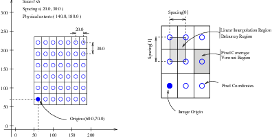
Figure 5.1: Geometrical concepts associated with the OTB image.
This chapter introduces the basic classes responsible for representing data in OTB. The most common classes are the otb::Image , the itk::Mesh and the itk::PointSet .
The otb::Image class follows the spirit of Generic Programming, where types are separated from the algorithmic behavior of the class. OTB supports images with any pixel type and any spatial dimension.
The source code for this example can be found in the file
Examples/DataRepresentation/Image/Image1.cxx.
This example illustrates how to manually construct an otb::Image class. The following is the minimal code needed to instantiate, declare and create the image class.
First, the header file of the Image class must be included.
Then we must decide with what type to represent the pixels and what the dimension of the image will be. With these two parameters we can instantiate the image class. Here we create a 2D image, which is what we often use in remote sensing applications, anyway, with unsigned short pixel data.
The image can then be created by invoking the New() operator from the corresponding image type and assigning the result to a itk::SmartPointer .
In OTB, images exist in combination with one or more regions. A region is a subset of the image and indicates a portion of the image that may be processed by other classes in the system. One of the most common regions is the LargestPossibleRegion, which defines the image in its entirety. Other important regions found in OTB are the BufferedRegion, which is the portion of the image actually maintained in memory, and the RequestedRegion, which is the region requested by a filter or other class when operating on the image.
In OTB, manually creating an image requires that the image is instantiated as previously shown, and that regions describing the image are then associated with it.
A region is defined by two classes: the itk::Index and itk::Size classes. The origin of the region within the image with which it is associated is defined by Index. The extent, or size, of the region is defined by Size. Index is represented by a n-dimensional array where each component is an integer indicating—in topological image coordinates—the initial pixel of the image. When an image is created manually, the user is responsible for defining the image size and the index at which the image grid starts. These two parameters make it possible to process selected regions.
The starting point of the image is defined by an Index class that is an n-dimensional array where each component is an integer indicating the grid coordinates of the initial pixel of the image.
The region size is represented by an array of the same dimension of the image (using the Size class). The components of the array are unsigned integers indicating the extent in pixels of the image along every dimension.
Having defined the starting index and the image size, these two parameters are used to create an ImageRegion object which basically encapsulates both concepts. The region is initialized with the starting index and size of the image.
Finally, the region is passed to the Image object in order to define its extent and origin. The SetRegions method sets the LargestPossibleRegion, BufferedRegion, and RequestedRegion simultaneously. Note that none of the operations performed to this point have allocated memory for the image pixel data. It is necessary to invoke the Allocate() method to do this. Allocate does not require any arguments since all the information needed for memory allocation has already been provided by the region.
In practice it is rare to allocate and initialize an image directly. Images are typically read from a source, such a file or data acquisition hardware. The following example illustrates how an image can be read from a file.
The source code for this example can be found in the file
Examples/DataRepresentation/Image/Image2.cxx.
The first thing required to read an image from a file is to include the header file of the otb::ImageFileReader class.
Then, the image type should be defined by specifying the type used to represent pixels and the dimensions of the image.
Using the image type, it is now possible to instantiate the image reader class. The image type is used as a template parameter to define how the data will be represented once it is loaded into memory. This type does not have to correspond exactly to the type stored in the file. However, a conversion based on C-style type casting is used, so the type chosen to represent the data on disk must be sufficient to characterize it accurately. Readers do not apply any transformation to the pixel data other than casting from the pixel type of the file to the pixel type of the ImageFileReader. The following illustrates a typical instantiation of the ImageFileReader type.
The reader type can now be used to create one reader object. A itk::SmartPointer (defined by the ::Pointer notation) is used to receive the reference to the newly created reader. The New() method is invoked to create an instance of the image reader.
The minimum information required by the reader is the filename of the image to be loaded in memory. This is provided through the SetFileName() method. The file format here is inferred from the filename extension. The user may also explicitly specify the data format explicitly using the itk::ImageIO (See Chapter 6.1 149 for more information):
Reader objects are referred to as pipeline source objects; they respond to pipeline update requests and initiate the data flow in the pipeline. The pipeline update mechanism ensures that the reader only executes when a data request is made to the reader and the reader has not read any data. In the current example we explicitly invoke the Update() method because the output of the reader is not connected to other filters. In normal application the reader’s output is connected to the input of an image filter and the update invocation on the filter triggers an update of the reader. The following line illustrates how an explicit update is invoked on the reader.
Access to the newly read image can be gained by calling the GetOutput() method on the reader. This method can also be called before the update request is sent to the reader. The reference to the image will be valid even though the image will be empty until the reader actually executes.
Any attempt to access image data before the reader executes will yield an image with no pixel data. It is likely that a program crash will result since the image will not have been properly initialized.
The source code for this example can be found in the file
Examples/DataRepresentation/Image/Image3.cxx.
This example illustrates the use of the SetPixel() and GetPixel() methods. These two methods provide direct access to the pixel data contained in the image. Note that these two methods are relatively slow and should not be used in situations where high-performance access is required. Image iterators are the appropriate mechanism to efficiently access image pixel data.
The individual position of a pixel inside the image is identified by a unique index. An index is an array of integers that defines the position of the pixel along each coordinate dimension of the image. The IndexType is automatically defined by the image and can be accessed using the scope operator like itk::Index . The length of the array will match the dimensions of the associated image.
The following code illustrates the declaration of an index variable and the assignment of values to each of its components. Please note that Index does not use SmartPointers to access it. This is because Index is a light-weight object that is not intended to be shared between objects. It is more efficient to produce multiple copies of these small objects than to share them using the SmartPointer mechanism.
The following lines declare an instance of the index type and initialize its content in order to associate it with a pixel position in the image.
Having defined a pixel position with an index, it is then possible to access the content of the pixel in the image. The GetPixel() method allows us to get the value of the pixels.
The SetPixel() method allows us to set the value of the pixel.
Please note that GetPixel() returns the pixel value using copy and not reference semantics. Hence, the method cannot be used to modify image data values.
Remember that both SetPixel() and GetPixel() are inefficient and should only be used for debugging or for supporting interactions like querying pixel values by clicking with the mouse.
The source code for this example can be found in the file
Examples/DataRepresentation/Image/Image4.cxx.
Even though OTB can be used to perform general image processing tasks, the primary purpose of the toolkit is the processing of remote sensing image data. In that respect, additional information about the images is considered mandatory. In particular the information associated with the physical spacing between pixels and the position of the image in space with respect to some world coordinate system are extremely important.
Image origin and spacing are fundamental to many applications. Registration, for example, is performed in physical coordinates. Improperly defined spacing and origins will result in inconsistent results in such processes. Remote sensing images with no spatial information should not be used for image analysis, feature extraction, GIS input, etc. In other words, remote sensing images lacking spatial information are not only useless but also hazardous.
Figure 5.1 illustrates the main geometrical concepts associated with the otb::Image . In this figure, circles are used to represent the center of pixels. The value of the pixel is assumed to exist as a Dirac Delta Function located at the pixel center. Pixel spacing is measured between the pixel centers and can be different along each dimension. The image origin is associated with the coordinates of the first pixel in the image. A pixel is considered to be the rectangular region surrounding the pixel center holding the data value. This can be viewed as the Voronoi region of the image grid, as illustrated in the right side of the figure. Linear interpolation of image values is performed inside the Delaunay region whose corners are pixel centers.
Image spacing is represented in a FixedArray whose size matches the dimension of the image. In order to manually set the spacing of the image, an array of the corresponding type must be created. The elements of the array should then be initialized with the spacing between the centers of adjacent pixels. The following code illustrates the methods available in the Image class for dealing with spacing and origin.
The array can be assigned to the image using the SetSignedSpacing() method.
The spacing information can be retrieved from an image by using the GetSignedSpacing() method. This method returns a reference to a FixedArray. The returned object can then be used to read the contents of the array. Note the use of the const keyword to indicate that the array will not be modified.
The image origin is managed in a similar way to the spacing. A Point of the appropriate dimension must first be allocated. The coordinates of the origin can then be assigned to every component. These coordinates correspond to the position of the first pixel of the image with respect to an arbitrary reference system in physical space. It is the user’s responsibility to make sure that multiple images used in the same application are using a consistent reference system. This is extremely important in image registration applications.
The following code illustrates the creation and assignment of a variable suitable for initializing the image origin.
The origin can also be retrieved from an image by using the GetOrigin() method. This will return a reference to a Point. The reference can be used to read the contents of the array. Note again the use of the const keyword to indicate that the array contents will not be modified.
Once the spacing and origin of the image have been initialized, the image will correctly map pixel indices to and from physical space coordinates. The following code illustrates how a point in physical space can be mapped into an image index for the purpose of reading the content of the closest pixel.
First, a itk::Point type must be declared. The point type is templated over the type used to represent coordinates and over the dimension of the space. In this particular case, the dimension of the point must match the dimension of the image.
The Point class, like an itk::Index , is a relatively small and simple object. For this reason, it is not reference-counted like the large data objects in OTB. Consequently, it is also not manipulated with itk::SmartPointer s. Point objects are simply declared as instances of any other C++ class. Once the point is declared, its components can be accessed using traditional array notation. In particular, the [] operator is available. For efficiency reasons, no bounds checking is performed on the index used to access a particular point component. It is the user’s responsibility to make sure that the index is in the range {0,Dimension-1}.
The image will map the point to an index using the values of the current spacing and origin. An index object must be provided to receive the results of the mapping. The index object can be instantiated by using the IndexType defined in the Image type.
The TransformPhysicalPointToIndex() method of the image class will compute the pixel index closest to the point provided. The method checks for this index to be contained inside the current buffered pixel data. The method returns a boolean indicating whether the resulting index falls inside the buffered region or not. The output index should not be used when the returned value of the method is false.
The following lines illustrate the point to index mapping and the subsequent use of the pixel index for accessing pixel data from the image.
Remember that GetPixel() and SetPixel() are very inefficient methods for accessing pixel data. Image iterators should be used when massive access to pixel data is required.
The source code for this example can be found in the file
Examples/IO/MetadataExample.cxx.
This example illustrates the access to metadata image information with OTB. By metadata, we mean data which is typically stored with remote sensing images, like geographical coordinates of pixels, pixel spacing or resolution, etc. Of course, the availability of these data depends on the image format used and on the fact that the image producer must fill the available metadata fields. The image formats which typically support metadata are for example CEOS and GeoTiff.
The metadata support is embedded in OTB’s IO functionnalities and is accessible through the otb::Image and otb::VectorImage classes. You should avoid using the itk::Image class if you want to have metadata support.
This simple example will consist on reading an image from a file and writing the metadata to an output ASCII file. As usual we start by defining the types needed for the image to be read.
We can now instantiate the reader and get a pointer to the input image.
Once the image has been read, we can access the metadata information. We will copy this information to an ASCII file, so we create an output file stream for this purpose.
We can now call the different available methods for accessing the metadata. Useful methods are :
One can also get the GCPs by number, as well as their coordinates in image and geographical space.
If a geographical transformation is available, it can be recovered as follows.
The term RGB (Red, Green, Blue) stands for a color representation commonly used in digital imaging. RGB is a representation of the human physiological capability to analyze visual light using three spectral-selective sensors [92, 145]. The human retina possess different types of light sensitive cells. Three of them, known as cones, are sensitive to color [51] and their regions of sensitivity loosely match regions of the spectrum that will be perceived as red, green and blue respectively. The rods on the other hand provide no color discrimination and favor high resolution and high sensitivity1 . A fifth type of receptors, the ganglion cells, also known as circadian2 receptors are sensitive to the lighting conditions that differentiate day from night. These receptors evolved as a mechanism for synchronizing the physiology with the time of the day. Cellular controls for circadian rythms are present in every cell of an organism and are known to be exquisitively precise [89].
The RGB space has been constructed as a representation of a physiological response to light by the three types of cones in the human eye. RGB is not a Vector space. For example, negative numbers are not appropriate in a color space because they will be the equivalent of “negative stimulation” on the human eye. In the context of colorimetry, negative color values are used as an artificial construct for color comparison in the sense that
 | (5.1) |
just as a way of saying that we can produce ColorB by combining ColorA and ColorC. However, we must be aware that (at least in emitted light) it is not possible to subtract light. So when we mention Equation 5.1 we actually mean
 | (5.2) |
On the other hand, when dealing with printed color and with paint, as opposed to emitted light like in computer screens, the physical behavior of color allows for subtraction. This is because strictly speaking the objects that we see as red are those that absorb all light frequencies except those in the red section of the spectrum [145].
The concept of addition and subtraction of colors has to be carefully interpreted. In fact, RGB has a different definition regarding whether we are talking about the channels associated to the three color sensors of the human eye, or to the three phosphors found in most computer monitors or to the color inks that are used for printing reproduction. Color spaces are usually non linear and do not even from a Group. For example, not all visible colors can be represented in RGB space [145].
ITK introduces the itk::RGBPixel type as a support for representing the values of an RGB color space. As such, the RGBPixel class embodies a different concept from the one of an itk::Vector in space. For this reason, the RGBPixel lack many of the operators that may be naively expected from it. In particular, there are no defined operations for subtraction or addition.
When you anticipate to perform the operation of “Mean” on a RGB type you are assuming that in the color space provides the action of finding a color in the middle of two colors, can be found by using a linear operation between their numerical representation. This is unfortunately not the case in color spaces due to the fact that they are based on a human physiological response [92].
If you decide to interpret RGB images as simply three independent channels then you should rather use the itk::Vector type as pixel type. In this way, you will have access to the set of operations that are defined in Vector spaces. The current implementation of the RGBPixel in ITK presumes that RGB color images are intended to be used in applications where a formal interpretation of color is desired, therefore only the operations that are valid in a color space are available in the RGBPixel class.
The following example illustrates how RGB images can be represented in OTB.
The source code for this example can be found in the file
Examples/DataRepresentation/Image/RGBImage.cxx.
Thanks to the flexibility offered by the Generic Programming style on which OTB is based, it is possible to instantiate images of arbitrary pixel type. The following example illustrates how a color image with RGB pixels can be defined.
A class intended to support the RGB pixel type is available in ITK. You could also define your own pixel class and use it to instantiate a custom image type. In order to use the itk::RGBPixel class, it is necessary to include its header file.
The RGB pixel class is templated over a type used to represent each one of the red, green and blue pixel components. A typical instantiation of the templated class is as follows.
The type is then used as the pixel template parameter of the image.
The image type can be used to instantiate other filter, for example, an otb::ImageFileReader object that will read the image from a file.
Access to the color components of the pixels can now be performed using the methods provided by the RGBPixel class.
The subindex notation can also be used since the itk::RGBPixel inherits the [] operator from the itk::FixedArray class.
The source code for this example can be found in the file
Examples/DataRepresentation/Image/VectorImage.cxx.
Many image processing tasks require images of non-scalar pixel type. A typical example is a multispectral image. The following code illustrates how to instantiate and use an image whose pixels are of vector type.
We could use the itk::Vector class to define the pixel type. The Vector class is intended to represent a geometrical vector in space. It is not intended to be used as an array container like the std::vector in STL. If you are interested in containers, the itk::VectorContainer class may provide the functionality you want.
However, the itk::Vector is a fixed size array and it assumes that the number of channels of the image is known at compile time. Therefore, we prefer to use the otb::VectorImage class which allows choosing the number of channels of the image at runtime. The pixels will be of type itk::VariableLengthVector .
The first step is to include the header file of the VectorImage class.
The VectorImage class is templated over the type used to represent the coordinate in space and over the dimension of the space. In this example, we want to represent Pléiades images which have 4 bands.
Since the pixel dimensionality is chosen at runtime, one has to pass this parameter to the image before memory allocation.
The VariableLengthVector class overloads the operator []. This makes it possible to access the Vector’s components using index notation. The user must not forget to allocate the memory for each individual pixel by using the Reserve method.
We can now store this vector in one of the image pixels by defining an index and invoking the SetPixel() method.
The GetPixel method can also be used to read Vectors pixels from the image
Lets repeat that both SetPixel() and GetPixel() are inefficient and should only be used for debugging purposes or for implementing interactions with a graphical user interface such as querying pixel value by clicking with the mouse.
The source code for this example can be found in the file
Examples/DataRepresentation/Image/Image5.cxx.
This example illustrates how to import data into the otb::Image class. This is particularly useful for interfacing with other software systems. Many systems use a contiguous block of memory as a buffer for image pixel data. The current example assumes this is the case and feeds the buffer into an otb::ImportImageFilter , thereby producing an Image as output.
For fun we create a synthetic image with a centered sphere in a locally allocated buffer and pass this block of memory to the ImportImageFilter. This example is set up so that on execution, the user must provide the name of an output file as a command-line argument.
First, the header file of the ImportImageFilter class must be included.
Next, we select the data type to use to represent the image pixels. We assume that the external block of memory uses the same data type to represent the pixels.
The type of the ImportImageFilter is instantiated in the following line.
A filter object created using the New() method is then assigned to a SmartPointer.
This filter requires the user to specify the size of the image to be produced as output. The SetRegion() method is used to this end. The image size should exactly match the number of pixels available in the locally allocated buffer.
The origin of the output image is specified with the SetOrigin() method.
The spacing of the image is passed with the SetSpacing() method.
Next we allocate the memory block containing the pixel data to be passed to the ImportImageFilter. Note that we use exactly the same size that was specified with the SetRegion() method. In a practical application, you may get this buffer from some other library using a different data structure to represent the images.
Here we fill up the buffer with a binary sphere. We use simple for() loops here similar to those found in the C or FORTRAN programming languages. Note that otb does not use for() loops in its internal code to access pixels. All pixel access tasks are instead performed using otb::ImageIterator s that support the management of n-dimensional images.
The buffer is passed to the ImportImageFilter with the SetImportPointer(). Note that the last argument of this method specifies who will be responsible for deleting the memory block once it is no longer in use. A false value indicates that the ImportImageFilter will not try to delete the buffer when its destructor is called. A true value, on the other hand, will allow the filter to delete the memory block upon destruction of the import filter.
For the ImportImageFilter to appropriately delete the memory block, the memory must be allocated with the C++ new() operator. Memory allocated with other memory allocation mechanisms, such as C malloc or calloc, will not be deleted properly by the ImportImageFilter. In other words, it is the application programmer’s responsibility to ensure that ImportImageFilter is only given permission to delete the C++ new operator-allocated memory.
Finally, we can connect the output of this filter to a pipeline. For simplicity we just use a writer here, but it could be any other filter.
Note that we do not call delete on the buffer since we pass true as the last argument of SetImportPointer(). Now the buffer is owned by the ImportImageFilter.
The source code for this example can be found in the file
Examples/DataRepresentation/Image/ImageListExample.cxx.
This example illustrates the use of the otb::ImageList class. This class provides the functionnalities needed in order to integrate image lists as data objects into the OTB pipeline. Indeed, if a std::list< ImageType > was used, the update operations on the pipeline might not have the desired effects.
In this example, we will only present the basic operations which can be applied on an otb::ImageList object.
The first thing required to read an image from a file is to include the header file of the otb::ImageFileReader class.
As usual, we start by defining the types for the pixel and image types, as well as those for the readers and writers.
We can now define the type for the image list. The otb::ImageList class is templated over the type of image contained in it. This means that all images in a list must have the same type.
Let us assume now that we want to read an image from a file and store it in a list. The first thing to do is to instantiate the reader and set the image file name. We effectively read the image by calling the Update().
We create an image list by using the New() method.
In order to store the image in the list, the PushBack() method is used.
We could repeat this operation for other readers or the outputs of filters. We will now write an image of the list to a file. We therefore instantiate a writer, set the image file name and set the input image for it. This is done by calling the Back() method of the list, which allows us to get the last element.
Other useful methods are:
Also, iterator classes are defined in order to have an efficient mean of moving through the list. Finally, the otb::ImageListToImageListFilter is provided in order to implement filter which operate on image lists and produce image lists.
The source code for this example can be found in the file
Examples/DataRepresentation/Mesh/PointSet1.cxx.
The itk::PointSet is a basic class intended to represent geometry in the form of a set of points in n-dimensional space. It is the base class for the itk::Mesh providing the methods necessary to manipulate sets of point. Points can have values associated with them. The type of such values is defined by a template parameter of the itk::PointSet class (i.e., TPixelType. Two basic interaction styles of PointSets are available in ITK. These styles are referred to as static and dynamic. The first style is used when the number of points in the set is known in advance and is not expected to change as a consequence of the manipulations performed on the set. The dynamic style, on the other hand, is intended to support insertion and removal of points in an efficient manner. Distinguishing between the two styles is meant to facilitate the fine tuning of a PointSet’s behavior while optimizing performance and memory management.
In order to use the PointSet class, its header file should be included.
Then we must decide what type of value to associate with the points. This is generally called the PixelType in order to make the terminology consistent with the itk::Image. The PointSet is also templated over the dimension of the space in which the points are represented. The following declaration illustrates a typical instantiation of the PointSet class.
A PointSet object is created by invoking the New() method on its type. The resulting object must be assigned to a SmartPointer. The PointSet is then reference-counted and can be shared by multiple objects. The memory allocated for the PointSet will be released when the number of references to the object is reduced to zero. This simply means that the user does not need to be concerned with invoking the Delete() method on this class. In fact, the Delete() method should never be called directly within any of the reference-counted ITK classes.
Following the principles of Generic Programming, the PointSet class has a set of associated defined types to ensure that interacting objects can be declared with compatible types. This set of type definitions is commonly known as a set of traits. Among them we can find the PointType type, for example. This is the type used by the point set to represent points in space. The following declaration takes the point type as defined in the PointSet traits and renames it to be conveniently used in the global namespace.
The PointType can now be used to declare point objects to be inserted in the PointSet. Points are fairly small objects, so it is inconvenient to manage them with reference counting and smart pointers. They are simply instantiated as typical C++ classes. The Point class inherits the [] operator from the itk::Array class. This makes it possible to access its components using index notation. For efficiency’s sake no bounds checking is performed during index access. It is the user’s responsibility to ensure that the index used is in the range {0,Dimension-1}. Each of the components in the point is associated with space coordinates. The following code illustrates how to instantiate a point and initialize its components.
Points are inserted in the PointSet by using the SetPoint() method. This method requires the user to provide a unique identifier for the point. The identifier is typically an unsigned integer that will enumerate the points as they are being inserted. The following code shows how three points are inserted into the PointSet.
It is possible to query the PointSet in order to determine how many points have been inserted into it. This is done with the GetNumberOfPoints() method as illustrated below.
Points can be read from the PointSet by using the GetPoint() method and the integer identifier. The point is stored in a pointer provided by the user. If the identifier provided does not match an existing point, the method will return false and the contents of the point will be invalid. The following code illustrates point access using defensive programming.
GetPoint() and SetPoint() are not the most efficient methods to access points in the PointSet. It is preferable to get direct access to the internal point container defined by the traits and use iterators to walk sequentially over the list of points (as shown in the following example).
The source code for this example can be found in the file
Examples/DataRepresentation/Mesh/PointSet2.cxx.
The itk::PointSet class uses an internal container to manage the storage of itk::Point s. It is more efficient, in general, to manage points by using the access methods provided directly on the points container. The following example illustrates how to interact with the point container and how to use point iterators.
The type is defined by the traits of the PointSet class. The following line conveniently takes the PointsContainer type from the PointSet traits and declare it in the global namespace.
The actual type of the PointsContainer depends on what style of PointSet is being used. The dynamic PointSet use the itk::MapContainer while the static PointSet uses the itk::VectorContainer . The vector and map containers are basically ITK wrappers around the STL classes std::map and std::vector. By default, the PointSet uses a static style, hence the default type of point container is an VectorContainer. Both the map and vector container are templated over the type of the elements they contain. In this case they are templated over PointType. Containers are reference counted object. They are then created with the New() method and assigned to a itk::SmartPointer after creation. The following line creates a point container compatible with the type of the PointSet from which the trait has been taken.
Points can now be defined using the PointType trait from the PointSet.
The created points can be inserted in the PointsContainer using the generic method InsertElement() which requires an identifier to be provided for each point.
Finally the PointsContainer can be assigned to the PointSet. This will substitute any previously existing PointsContainer on the PointSet. The assignment is done using the SetPoints() method.
The PointsContainer object can be obtained from the PointSet using the GetPoints() method. This method returns a pointer to the actual container owned by the PointSet which is then assigned to a SmartPointer.
The most efficient way to sequentially visit the points is to use the iterators provided by PointsContainer. The Iterator type belongs to the traits of the PointsContainer classes. It behaves pretty much like the STL iterators.3 The Points iterator is not a reference counted class, so it is created directly from the traits without using SmartPointers.
The subsequent use of the iterator follows what you may expect from a STL iterator. The iterator to the first point is obtained from the container with the Begin() method and assigned to another iterator.
The ++ operator on the iterator can be used to advance from one point to the next. The actual value of the Point to which the iterator is pointing can be obtained with the Value() method. The loop for walking through all the points can be controlled by comparing the current iterator with the iterator returned by the End() method of the PointsContainer. The following lines illustrate the typical loop for walking through the points.
Note that as in STL, the iterator returned by the End() method is not a valid iterator. This is called a past-end iterator in order to indicate that it is the value resulting from advancing one step after visiting the last element in the container.
The number of elements stored in a container can be queried with the Size() method. In the case of the PointSet, the following two lines of code are equivalent, both of them returning the number of points in the PointSet.
The source code for this example can be found in the file
Examples/DataRepresentation/Mesh/PointSet3.cxx.
The itk::PointSet class was designed to interact with the Image class. For this reason it was found convenient to allow the points in the set to hold values that could be computed from images. The value associated with the point is referred as PixelType in order to make it consistent with image terminology. Users can define the type as they please thanks to the flexibility offered by the Generic Programming approach used in the toolkit. The PixelType is the first template parameter of the PointSet.
The following code defines a particular type for a pixel type and instantiates a PointSet class with it.
Data can be inserted into the PointSet using the SetPointData() method. This method requires the user to provide an identifier. The data in question will be associated to the point holding the same identifier. It is the user’s responsibility to verify the appropriate matching between inserted data and inserted points. The following line illustrates the use of the SetPointData() method.
Data associated with points can be read from the PointSet using the GetPointData() method. This method requires the user to provide the identifier to the point and a valid pointer to a location where the pixel data can be safely written. In case the identifier does not match any existing identifier on the PointSet the method will return false and the pixel value returned will be invalid. It is the user’s responsibility to check the returned boolean value before attempting to use it.
The SetPointData() and GetPointData() methods are not the most efficient way to get access to point data. It is far more efficient to use the Iterators provided by the PointDataContainer.
Data associated with points is internally stored in PointDataContainers. In the same way as with points, the actual container type used depend on whether the style of the PointSet is static or dynamic. Static point sets will use an itk::VectorContainer while dynamic point sets will use an itk::MapContainer . The type of the data container is defined as one of the traits in the PointSet. The following declaration illustrates how the type can be taken from the traits and used to conveniently declare a similar type on the global namespace.
Using the type it is now possible to create an instance of the data container. This is a standard reference counted object, henceforth it uses the New() method for creation and assigns the newly created object to a SmartPointer.
Pixel data can be inserted in the container with the method InsertElement(). This method requires an identified to be provided for each point data.
Finally the PointDataContainer can be assigned to the PointSet. This will substitute any previously existing PointDataContainer on the PointSet. The assignment is done using the SetPointData() method.
The PointDataContainer can be obtained from the PointSet using the GetPointData() method. This method returns a pointer (assigned to a SmartPointer) to the actual container owned by the PointSet.
The most efficient way to sequentially visit the data associated with points is to use the iterators provided by PointDataContainer. The Iterator type belongs to the traits of the PointsContainer classes. The iterator is not a reference counted class, so it is just created directly from the traits without using SmartPointers.
The subsequent use of the iterator follows what you may expect from a STL iterator. The iterator to the first point is obtained from the container with the Begin() method and assigned to another iterator.
The ++ operator on the iterator can be used to advance from one data point to the next. The actual value of the PixelType to which the iterator is pointing can be obtained with the Value() method. The loop for walking through all the point data can be controlled by comparing the current iterator with the iterator returned by the End() method of the PointsContainer. The following lines illustrate the typical loop for walking through the point data.
Note that as in STL, the iterator returned by the End() method is not a valid iterator. This is called a past-end iterator in order to indicate that it is the value resulting from advancing one step after visiting the last element in the container.
The source code for this example can be found in the file
Examples/DataRepresentation/Mesh/PointSetWithVectors.cxx.
This example illustrates how a point set can be parameterized to manage a particular pixel type. It is quite common to associate vector values with points for producing geometric representations or storing multi-band information. The following code shows how vector values can be used as pixel type on the PointSet class. The itk::Vector class is used here as the pixel type. This class is appropriate for representing the relative position between two points. It could then be used to manage displacements in disparity map estimations, for example.
In order to use the vector class it is necessary to include its header file along with the header of the point set.
The Vector class is templated over the type used to represent the spatial coordinates and over the space dimension. Since the PixelType is independent of the PointType, we are free to select any dimension for the vectors to be used as pixel type. However, for the sake of producing an interesting example, we will use vectors that represent displacements of the points in the PointSet. Those vectors are then selected to be of the same dimension as the PointSet.
Then we use the PixelType (which are actually Vectors) to instantiate the PointSet type and subsequently create a PointSet object.
The following code is generating a circle and assigning vector values to the points. The components of the vectors in this example are computed to represent the tangents to the circle as shown in Figure ??.
We can now visit all the points and use the vector on the pixel values to apply a displacement on the points. This is along the spirit of what a deformable model could do at each one of its iterations.
Note that the ConstIterator was used here instead of the normal Iterator since the pixel values are only intended to be read and not modified. ITK supports const-correctness at the API level.
The itk::Vector class has overloaded the + operator with the itk::Point . In other words, vectors can be added to points in order to produce new points. This property is exploited in the center of the loop in order to update the points positions with a single statement.
We can finally visit all the points and print out the new values
Note that itk::Vector is not the appropriate class for representing normals to surfaces and gradients of functions. This is due to the way in which vectors behave under affine transforms. ITK has a specific class for representing normals and function gradients. This is the itk::CovariantVector class.
The source code for this example can be found in the file
Examples/DataRepresentation/Mesh/Mesh1.cxx.
The itk::Mesh class is intended to represent shapes in space. It derives from the itk::PointSet class and hence inherits all the functionality related to points and access to the pixel-data associated with the points. The mesh class is also n-dimensional which allows a great flexibility in its use.
In practice a Mesh class can be seen as a PointSet to which cells (also known as elements) of many different dimensions and shapes have been added. Cells in the mesh are defined in terms of the existing points using their point-identifiers.
In the same way as for the PointSet, two basic styles of Meshes are available in ITK. They are referred to as static and dynamic. The first one is used when the number of points in the set can be known in advance and it is not expected to change as a consequence of the manipulations performed on the set. The dynamic style, on the other hand, is intended to support insertion and removal of points in an efficient manner. The reason for making the distinction between the two styles is to facilitate fine tuning its behavior with the aim of optimizing performance and memory management. In the case of the Mesh, the dynamic/static aspect is extended to the management of cells.
In order to use the Mesh class, its header file should be included.
Then, the type associated with the points must be selected and used for instantiating the Mesh type.
The Mesh type extensively uses the capabilities provided by Generic Programming. In particular the Mesh class is parameterized over the PixelType and the dimension of the space. PixelType is the type of the value associated with every point just as is done with the PointSet. The following line illustrates a typical instantiation of the Mesh.
Meshes are expected to take large amounts of memory. For this reason they are reference counted objects and are managed using SmartPointers. The following line illustrates how a mesh is created by invoking the New() method of the MeshType and the resulting object is assigned to a itk::SmartPointer .
The management of points in the Mesh is exactly the same as in the PointSet. The type point associated with the mesh can be obtained through the PointType trait. The following code shows the creation of points compatible with the mesh type defined above and the assignment of values to its coordinates.
The points can now be inserted in the Mesh using the SetPoint() method. Note that points are copied into the mesh structure. This means that the local instances of the points can now be modified without affecting the Mesh content.
The current number of points in the Mesh can be queried with the GetNumberOfPoints() method.
The points can now be efficiently accessed using the Iterator to the PointsContainer as it was done in the previous section for the PointSet. First, the point iterator type is extracted through the mesh traits.
A point iterator is initialized to the first point with the Begin() method of the PointsContainer.
The ++ operator on the iterator is now used to advance from one point to the next. The actual value of the Point to which the iterator is pointing can be obtained with the Value() method. The loop for walking through all the points is controlled by comparing the current iterator with the iterator returned by the End() method of the PointsContainer. The following lines illustrate the typical loop for walking through the points.
The source code for this example can be found in the file
Examples/DataRepresentation/Mesh/Mesh2.cxx.
A itk::Mesh can contain a variety of cell types. Typical cells are the itk::LineCell , itk::TriangleCell , itk::QuadrilateralCell and itk::TetrahedronCell . The latter will not be used very often in the remote sensing context. Additional flexibility is provided for managing cells at the price of a bit more of complexity than in the case of point management.
The following code creates a polygonal line in order to illustrate the simplest case of cell management in a Mesh. The only cell type used here is the LineCell. The header file of this class has to be included.
In order to be consistent with the Mesh, cell types have to be configured with a number of custom types taken from the mesh traits. The set of traits relevant to cells are packaged by the Mesh class into the CellType trait. This trait needs to be passed to the actual cell types at the moment of their instantiation. The following line shows how to extract the Cell traits from the Mesh type.
The LineCell type can now be instantiated using the traits taken from the Mesh.
The main difference in the way cells and points are managed by the Mesh is that points are stored by copy on the PointsContainer while cells are stored in the CellsContainer using pointers. The reason for using pointers is that cells use C++ polymorphism on the mesh. This means that the mesh is only aware of having pointers to a generic cell which is the base class of all the specific cell types. This architecture makes it possible to combine different cell types in the same mesh. Points, on the other hand, are of a single type and have a small memory footprint, which makes it efficient to copy them directly into the container.
Managing cells by pointers add another level of complexity to the Mesh since it is now necessary to establish a protocol to make clear who is responsible for allocating and releasing the cells’ memory. This protocol is implemented in the form of a specific type of pointer called the CellAutoPointer. This pointer, based on the itk::AutoPointer , differs in many respects from the SmartPointer. The CellAutoPointer has an internal pointer to the actual object and a boolean flag that indicates if the CellAutoPointer is responsible for releasing the cell memory whenever the time comes for its own destruction. It is said that a CellAutoPointer owns the cell when it is responsible for its destruction. Many CellAutoPointer can point to the same cell but at any given time, only one CellAutoPointer can own the cell.
The CellAutoPointer trait is defined in the MeshType and can be extracted as illustrated in the following line.
Note that the CellAutoPointer is pointing to a generic cell type. It is not aware of the actual type of the cell, which can be for example LineCell, TriangleCell or TetrahedronCell. This fact will influence the way in which we access cells later on.
At this point we can actually create a mesh and insert some points on it.
The following code creates two CellAutoPointers and initializes them with newly created cell objects. The actual cell type created in this case is LineCell. Note that cells are created with the normal new C++ operator. The CellAutoPointer takes ownership of the received pointer by using the method TakeOwnership(). Even though this may seem verbose, it is necessary in order to make it explicit from the code that the responsibility of memory release is assumed by the AutoPointer.
The LineCells should now be associated with points in the mesh. This is done using the identifiers assigned to points when they were inserted in the mesh. Every cell type has a specific number of points that must be associated with it.4 For example a LineCell requires two points, a TriangleCell requires three and a TetrahedronCell requires four. Cells use an internal numbering system for points. It is simply an index in the range {0,NumberOfPoints-1}. The association of points and cells is done by the SetPointId() method which requires the user to provide the internal index of the point in the cell and the corresponding PointIdentifier in the Mesh. The internal cell index is the first parameter of SetPointId() while the mesh point-identifier is the second.
Cells are inserted in the mesh using the SetCell() method. It requires an identifier and the AutoPointer to the cell. The Mesh will take ownership of the cell to which the AutoPointer is pointing. This is done internally by the SetCell() method. In this way, the destruction of the CellAutoPointer will not induce the destruction of the associated cell.
After serving as an argument of the SetCell() method, a CellAutoPointer no longer holds ownership of the cell. It is important not to use this same CellAutoPointer again as argument to SetCell() without first securing ownership of another cell.
The number of Cells currently inserted in the mesh can be queried with the GetNumberOfCells() method.
In a way analogous to points, cells can be accessed using Iterators to the CellsContainer in the mesh. The trait for the cell iterator can be extracted from the mesh and used to define a local type.
Then the iterators to the first and past-end cell in the mesh can be obtained respectively with the Begin() and End() methods of the CellsContainer. The CellsContainer of the mesh is returned by the GetCells() method.
Finally a standard loop is used to iterate over all the cells. Note the use of the Value() method used to get the actual pointer to the cell from the CellIterator. Note also that the values returned are pointers to the generic CellType. These pointers have to be down-casted in order to be used as actual LineCell types. Safe down-casting is performed with the dynamic_cast operator which will throw an exception if the conversion cannot be safely performed.
The source code for this example can be found in the file
Examples/DataRepresentation/Mesh/Mesh3.cxx.
In the same way that custom data can be associated with points in the mesh, it is also possible to associate custom data with cells. The type of the data associated with the cells can be different from the data type associated with points. By default, however, these two types are the same. The following example illustrates how to access data associated with cells. The approach is analogous to the one used to access point data.
Consider the example of a mesh containing lines on which values are associated with each line. The mesh and cell header files should be included first.
Then the PixelType is defined and the mesh type is instantiated with it.
The itk::LineCell type can now be instantiated using the traits taken from the Mesh.
Let’s now create a Mesh and insert some points into it. Note that the dimension of the points matches the dimension of the Mesh. Here we insert a sequence of points that look like a plot of the log() function.
A set of line cells is created and associated with the existing points by using point identifiers. In this simple case, the point identifiers can be deduced from cell identifiers since the line cells are ordered in the same way.
Data associated with cells is inserted in the itk::Mesh by using the SetCellData() method. It requires the user to provide an identifier and the value to be inserted. The identifier should match one of the inserted cells. In this simple example, the square of the cell identifier is used as cell data. Note the use of static_cast to PixelType in the assignment.
Cell data can be read from the Mesh with the GetCellData() method. It requires the user to provide the identifier of the cell for which the data is to be retrieved. The user should provide also a valid pointer to a location where the data can be copied.
Neither SetCellData() or GetCellData() are efficient ways to access cell data. More efficient access to cell data can be achieved by using the Iterators built into the CellDataContainer.
Note that the ConstIterator is used here because the data is only going to be read. This approach is exactly the same already illustrated for getting access to point data. The iterator to the first cell data item can be obtained with the Begin() method of the CellDataContainer. The past-end iterator is returned by the End() method. The cell data container itself can be obtained from the mesh with the method GetCellData().
Finally a standard loop is used to iterate over all the cell data entries. Note the use of the Value() method used to get the actual value of the data entry. PixelType elements are copied into the local variable cellValue.
More details about the use of itk::Mesh can be found in the ITK Software Guide.
The source code for this example can be found in the file
Examples/DataRepresentation/Path/PolyLineParametricPath1.cxx.
This example illustrates how to use the itk::PolyLineParametricPath . This class will typically be used for representing in a concise way the output of an image segmentation algorithm in 2D. See section 14.3 for an example in the context of alignment detection. The PolyLineParametricPath however could also be used for representing any open or close curve in N-Dimensions as a linear piece-wise approximation.
First, the header file of the PolyLineParametricPath class must be included.
The path is instantiated over the dimension of the image.
2;rgb:0000/0000/0000